Viewed products


Confianza Online


domoticalia.es/es/ Reviews with ekomi.es

HELTUN - 16A Z-Wave + 700 high charge switch module

HE-HLS01

New

Heltun's high power switch module is a Z-Wave + device with thermostatic functions. It is also suitable for luminaires or fixtures up to 16A.

More details

Out of stock

69,99 €

Technical characteristics

Technology Z-Wave Plus

More info

YOUR COMFORT MATTERS.

What are the most important aspects of your comfort? Is it the general room temperature? Remote or automatic control of appliances, sockets or groups of lights? Or maybe something else? Whatever the need, HELTUN guarantees that it will take care of it.

Take control

HELTUN's advanced zero-crossing technology offers a significant increase in system longevity and reliability. The relay supports a maximum load of 16 amps and is suitable for controlling electric heating, as well as electrical outlets, appliances or lights.

Incredibly small and smart

The heavy-duty switch with thermostat functions brings incredible capabilities to any connected appliance. Makes electrical outlets and lights "smart" with advanced remote control, control, and programmability. You can now enable internet-connected thermostat functions in cases where the display and local controls are not required, such as rooftop or driveway defrosting systems, etc. This brings the convenience of smartphone application control and programming to "dumb" devices such as electrical outlets and panels, electric water heaters, radiators, fireplaces, and underfloor or underfloor defrosting systems.

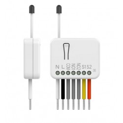
At 26mm deep, the switch module is also incredibly small, fitting into any rectangular, round or square electrical junction box, even behind a connected device.

Inputs, outputs and sensors

You can connect an NTC temperature sensor to monitor the ambient or radiant temperatures of the floor / ceiling system. This sensor can be installed on the wall, under the floor or on the ceiling, allowing you to accurately measure surface temperatures. The HELTUN Heavy Duty Switch Module is fully compatible with third-party NTC sensors, so there is no need to replace an existing sensor when installing.

You can also control the module by connecting it to an external system - such as an alarm system - using a pilot wire that could be programmed to automatically reduce the temperature when the house is empty or turn on the electrical outlets / lights when people come home.

Know your energy consumption
HELTUN's integrated power consumption system accurately monitors the amount of power that has passed through its high load switch module during a particular day, week or month. With the switch module, you can determine the amount of power used by major appliances, entertainment systems, computers, small appliances, or complete lighting systems.

Heltun has also designed the circuit to draw almost zero watts of power when in standby mode. This saves you energy and money even if your home is equipped with many HELTUN products.

Thermostat modes
Although the Heavy Duty Switch Module has no display or buttons, all of its thermostat functions are accessible through a Z-Wave controller. Here are the available thermostat modes.

COM (Comfort), ECO (Energy Saving) and VAC (Vacation) modes maintain the temperature you have specified using the Z-Wave controller.

DRY mode switches to a higher temperature to heat quickly to dry floors after washing. The DRY mode returns to the previous mode after the specified time.

MAN (manual) mode allows you to override any current mode or program and manually turn the heater on or off using your controller interface.

See the controller manual for instructions on how to set the temperature set points and modes for the connected thermostats.

Time mode: Thermostat
You can reduce your electricity bill and help the environment simply by using the TIME mode through your Z-Wave controller. Adjust the comfort level of your home according to your family's habits by reducing the temperature while everyone is away and increasing it in the evenings and mornings.

People spend an average of 12 to 14 hours a day at home. The rest of the time, an empty house needs minimal heating. And since your family sleeps most of the time at home, you can make a big difference by setting your home comfort level at 18 ° C at night, which is considered the optimal temperature for sleeping.

Using the TIME mode and your controller, set different temperatures for morning, day, afternoon, or night. For example: "Morning" mode can start at 7:00 am at 23 ° C and then switch to "Day" at 8:30 am at 17 ° C when everyone is at work and school. The "Night" mode can start at 4:00 pm at 22 ° C and then switch to "Night" at 11:00 pm at 18 ° C. Adjusting the temperatures for these four periods can save a lot on your electric bill, and you can adjust the weekdays for the weekend days.

Time Mode: Other Devices
The heavy duty switch module can be connected to products other than those controlled by a thermostat, such as electrical panels, outlets, and lighting. The time mode provides an extremely powerful ability to schedule on and off cycles for groups of connected devices. Here are some ways that Time Mode can add convenience, comfort, security, and savings to your home:

Turn off electrical outlets connected to energy-consuming appliances such as washers, dryers, and dishwashers during periods when electricity is expensive.
Turn off your electric water heater / boiler on vacation or even at night and turn it on again in the morning.
Turn off electrical outlets when family members are at work or on vacation to prevent a fire from leaving an appliance running (kettle, iron, curling iron, etc.).
Pre-program all house and patio lights to turn on before visitors arrive at your vacation home.
And as with the thermostat functions of the high-power switch module, a controller can assign connected appliances to ON or OFF during the morning, day, afternoon or night periods. This can allow you to easily turn off the plugs connected to game consoles at night, or to program all exterior lights to turn on at night and in the morning. The possibilities are only limited by the creativity of the user.

Powerfully customizable
There are eight different modes that can be selected for the heavy duty switch module using a pilot wire to another device (e.g. alarm panel, wall switch, etc.):

Revert State - If on, off when circuit is closed (or if off, on).
Momentary - On when pilot wire circuit is closed, off when open.
Momentary Reverse - Off when pilot wire circuit is open, on when closed.
Switch Only - When the pilot wire circuit is closed (ie shorted).
Shutdown Only - When the pilot wire circuit is closed (i.e. shorted).
Change Mode - Change to a specific thermostat mode (preset in the settings menu).
The relay output of the Heavy Duty Switch Module can also be controlled by an internal timer. For example, after turning on the switch, it can be set to automatically turn off later (or vice versa: turn on after being turned off).

Timer (ON and OFF) - Lights when the pilot wire circuit closes, then turns off after a specified time.
Timer (OFF and ON) - Turns off when the pilot wire circuit closes, and turns on after a specified time.

Make your switches incredibly smart
Is your DIN rail a "stupid" rail?

Since the HELTUN Heavy Duty Switch Module can handle up to 16 amps, it is a perfect complement to your switch panel to monitor and control groups of devices from the Internet through a Z-Wave gateway, such as:

The sockets connected to the main devices
Plugs connected to small devices with high loads
Whole groups of sockets
Whole groups of lights
The mounting adapter is available as an accessory for the heavy duty switch module to fit standard DIN rails (50mm wide), or it can also be mounted directly to the wall using the supplied screws and plugs.

Security
The heavy duty switch module can improve the security of your home in a number of ways.

Overload - If the Heavy Duty Switch Module detects too much power from connected appliances - such as multiple connected electrical outlets - it will automatically shut down to protect itself from circuit overload. This is useful for many applications where multiple loads are connected to a heavy load switch module.

Overheating - The Heavy Duty Switch Module also continuously monitors temperature providing multiple layers of protection. With an external NTC sensor, it monitors the temperatures inside the junction box allowing automatic disconnection and notification to the user if a plug gets too hot. It can even warn the user of rising temperatures before reaching a critical shutdown level, after which it will automatically close the output when it crosses a dangerous threshold.

High Load Delay - If a family member leaves a high-energy appliance on for a long time - such as an iron plugged in for more than an hour - the High Load Switch Module can be configured to automatically turn off connected plugs to avoid a fire.

Users can set high load shutdown limits, time and temperature limits, and notification settings in the heavy duty switch module settings using a Z-wave controller.

Easy to install
The HELTUN heavy duty switch module can be easily installed in any standard electrical junction box (rectangular, square or round) in just a few minutes. Installation should only be carried out by a person trained in handling high voltage electrical systems.

Z-Wave Plus V2 certified
You can connect HELTUN devices to a home automation controller using the latest Z-Wave Plus V2 700 platform. HELTUN features advanced Smart Start technology for easy system integration and the S2 security framework with AES 256 encryption for seamless handover. secure data.

This heavy duty switch module is compatible with all certified Wave Z controllers and devices that correctly implement the Wave Z classes of switches and thermostats. With a Z-Wave controller, you can manage all the functions of the switch module via of a mobile application, including temperature and mode changes, displaying energy consumption graphs and much more.

Up to 10 separate devices can be connected to the HELTUN heavy duty switch module. You can combine it with any Z wave compatible on / off switch or any other switch to control different air conditioning systems in one room. You can even connect motion detectors and switch high load switching modes when people are detected in the house.

HELTUN units are compatible with all Z-Wave frequencies for different countries (Europe, Russia, Israel, Australia, USA, India, Hong Kong, China, Japan and Korea). The correct frequency can be selected in the device menu.

HELTUN periodically releases new firmware for the device with additional features that can be remotely updated through an encrypted OTA (Over-The-Air) process.

FUNCTIONS:

Inclusion / exclusion options in a Wave Z network:
It is not guaranted
S0 Safe ...
S2 not allowed, S2 allowed with key
Association control of 10 network devices
6 operating modes: COM, ECO, VAC, DRY, TIME, MANUAL
Four programs: morning, day, afternoon and night.
Program and set the temperature (heaters)
Programming only (other devices)
Eight retransmission modes (using a pilot wire to another device):
Reverse the state
Momentary
Invert momentarily
Turn on only
Turn off only
Switch to
Timer (ON and OFF)
Timer (OFF and ON)
Three security modes with notification and automatic shutdown:
Overload (automatic shutdown in case of overload)
Overheating (automatic shutdown in case of output overheating)
High load delay (notification and automatic shutdown when high load delay is exceeded)
It can be used with various NTC sensors: Resistance value range: 1k © - 100k ©
Calibrating the temperature sensor
Temperature setting ranges: 4 ° C - 37 ° C
Temperature limiter
Set the temperature hysteresis
Temperature measurement: Centigrade (° C) or Fahrenheit (° F)
Reset the energy consumption meter
Factory reset button
Updating the OTA (Over-The-Air) firmware
TECHNICAL DATA :

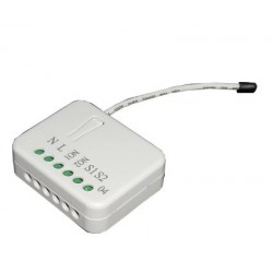
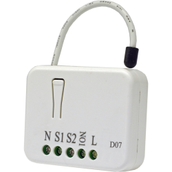
Dimensions: 50x50x26 mm
Material: Fire retardant plastic
White color
Operating temperature: 0 °! at + 60 °!
Power supply: 85-265VAC 50Hz / 60Hz, or 24-48VDC
Power Consumption: <1W
Maximum resistive load: 16,4000W @ 220V
Relay switching with HELTUN Advanced Zero Pass Technology
Relay life: 100,000 cycles
External soil temperature sensor
NTC 10k © (included)
Measurement range: -30 ° C to + 80 ° C
Accuracy: ± 0.5 ° C
Energy consumption meter
IP class: IP21
Z-Wave Plus V2 SDK: V7.11
Z Wave Module: ZGM130S
Assembly:
Electrical connection box: round, rectangular or square - minimum depth 40 mm.
Optional adapter for DIN rail mounting (50mm wide) or to screw into the wall

Extended Z-Wave info

Name: High Load Switch
Manufacturer:HELTUN
Identifier:HE-HLS01
Z-Wave Certification Number:ZC12-20070081
Hardware Plattform:ZGM130
FLiRS:NO
Role Type:Always On Slave
Short Description:Advanced Programmable Z-Wave Plus v2 In-Wall High Load Switch on the Z-Wave 700 platform. With 16 Amp load capacity, it is a perfect addition to any circuit breaker panel. Fits easily behind outlets or switches in standard electrical junction boxes. It can also provide Internet-connected thermostat functions where a local display and controls are not needed.
Description:The HELTUN HE-HLS01 is an advanced programmable Z-Wave Plus v2 in-wall high load switch that controls many devices, such as electrical outlets & panels, electric water heaters, radiators, fireplaces, and radiant floor or de-icing systems. It can also provide Internet-connected thermostat functions where a local display and controls are not needed. HELTUN HE-HLS01 fits easily behind outlets or switches in standard electrical junction boxes. Features: • 16A maximum load • 10 scenarios for output control • 6 thermostat operating modes • 4 association groups • External NTC sensor • Real time energy consumption meter • Onboard Real Time Clock (RTC) • 8 safety functions & notifications • Works both with VAC 85-265 and VDC 24-48 • Incorporates HELTUN Advanced Zero-Cross Technology The HELTUN HE-HLS01 is part of an entire line of smart, connected products designed to provide the best technology has to offer without compromising stylish living. Learn more about HELTUN products at www.heltun.com

Manual download HERE.

Group
Max Nodes
Description
1
1
This is the Lifeline Group 1 which sends status (lifeline) reports to the primary controller.
2
1
Group 2 – “Relay Basic Set”: is assigned to the HE-HT01 operating state. It sends a Basic Set command with value 0 (Off) when it goes to IDLE state and sends 255 (ON) when it goes into HEATING state.
3
1
Group 3 – “S1 Basic Set”: is assigned to the HE-HLS01 external input state. It sends a Basic Set command with value 255 (On) when external input is shorted and sends 0 (Off) when input is open.
4
1
Group 4 – “Temperature Sensor”: is assigned to the HE-HLS01 external temperature sensor and sends the sensor value when it changes.
Number
Size (Bytes)
Default Value
Name
Description
1
1
0
DEVICE TYPE
Device Type. This parameter is read only and indicates in which mode the device is included. The device can be included either in the Binary Switch mode or in the Thermostat mode. Use inclusion in Binary Switch mode if there is a need to control on/off device and use inclusion in Thermostat mode if there is a need to control heating system. For the appropriate inclusion process see the section Z-Wave Network of manual.
10
1
0
TEMPERATURE SCALE MODE
Temperature Scale Mode. This parameter determines in which unit of measurement (degrees Celsius or Fahrenheit) the device will report the temperature, and also determines the scale that will be interpreted by the configuration parameters. Note: This configuration parameter has impact on configuration parameters 9,12,16,17 and 32, 42-69 in thermostat mode. If scale is set to degrees Fahrenheit, configuration values at mentioned parameters will be automatically converted from Celsius to Fahrenheit and any change in the values will be interpreted as Fahrenheits.
11
1
10
TEMPERATURE REPORT INTERVAL
Temperature Sensor Consecutive Report Interval. This Parameter defines the interval between consecutive reports of temperature sensor reading to the gateway. Note: If the sensor readings change, the device will send the report to the gateway regardless of this parameter value. In order not to increase traffic on your network, it is not recommended to reduce the value of this parameter. We recommend reducing the value of this parameter only in case of poor connection, when reports from the device does not always reach the gateway.
12
1
5
TEMPERATURE REPORT THRESHOLD
Temperature Sensor Report Threshold. This parameter determines the change in temperature level resulting in temperature sensors report being sent to the gateway. In Celsius scale mode the value of this parameter should be x10, e.g. for 0.4°C use value 4. From 1 (0.1°C) to 100 (10°C) can be selected in Celsius scale mode and from 1 to 18 can be selected in Fahrenheit scale mode. The factory default value is 5 (0.5°) in °C scale and 1 in °F scale.
13
1
10
METER REPORT INTERVAL
Energy Consumption Meter Consecutive Report Interval. When the device is connected to the Z-Wave gateway (controller), it periodically sends to the gateway reports from its external temperature sensor and energy consumption meter even if there are not changes in the values. This Parameter defines the interval between consecutive reports of real time and cumulative energy consumption data to the gateway. Note: If the sensor readings change, the device will send the report to the gateway regardless of this parameter value. In order not to increase traffic on your network, it is not recommended to reduce the value of this parameter. We recommend reducing the value of this parameter only in case of poor connection, when reports from the device does not always reach the gateway. Note: Energy consumption meter function is available only if the device is AC powered.
131
1
0
LOAD ON NOTIFICATION
The actual parameter number is 31 when the device is in the 'Binary Switch' mode. Load Switched On Notification. If this function is enabled the device will send “AC Mains Re-Connected” notification to the gateway each time when the relay output state changes to On. Note: This function can be useful for informing in case of automatic control of the load by schedule or scenario.
132
1
1
LOAD OFF NOTIFICATION
The actual parameter number is 32 when the device is in the 'Binary Switch' mode. Load Switched Off Notification. If this function is enabled the device will send “AC Mains Disconnected” notification to the gateway each time when the relay output state changes to Off. Note: This function can be useful for informing when the device automatically switches the output Off because of emergency case or in case of automatic control of the load by schedule or scenario.
133
2
0
TIME LIMITITED LOAD
The actual parameter number is 33 when the device is in the 'Binary Switch' mode. High Load Timeout Protection: Power Threshold If the HLS01 is used to control an electric socket, you can configure the device so that it automatically switch Off the socket if the potentially dangerous high load is connected longer than allowable time (time to be set in the Parameter 34), for example, if you left the iron switched On for too long. Set in this parameter the threshold value in watts, reaching which the connected load will be considered high. Note: If the connected load power is less than value of this parameter, the protection will not be activated. Note: If the Parameter 34 (time threshold) value is set to 0, the protection will not be activated. Note: The time counter is reset every time when the load consumption drops to zero. Note: We recommend activating the Load Switched Off notification (the Parameter 32) to be informed when the device automatically switch Off the socket. Note: The protection works only if the device is AC powered.
134
2
0
HIGH LOAD ON TIME LIMIT
The actual parameter number is 34 when the device is in the 'Binary Switch' mode. High Load Timeout Protection: Time Threshold If High Load Timeout Protection is activated (the Parameter 33 is set) use this parameter to set the threshold value in minutes. If the load is connected longer than this value, the device will automatically switch Off the socket. Note: If the value of this parameter is set 0, the protection will not be activated. Note: If the connected load power is less than value of the Parameter 33, the protection will not be activated. Note: The time counter is reset every time when the load consumption drops to zero. If the connected load may change its consumption, make sure that the time threshold will be reached before the load consumption drops. Note: We recommend activating the Load Switched Off notification (the Parameter 32) to be informed when the device automatically switch Off the socket. Note: The protection works only if the device is AC powered.
135
1
0
LOAD AUTO ON/OFF
The actual parameter number is 35 when the device is in the 'Binary Switch' mode. Load Switched On Notification. Auto On/Off If this function is enabled the device will switch Off the relay output when there is no consumption and switch On the output again when the load is reconnected. It is possible to set the delay for Auto Off function (in the Parameter 36) and for Auto On function (in the Parameter 37). Note: If the output is manually switched Off (from Gateway or External Input toggle) Auto ON function will be blocked until the output switches back to ON manually or the load disconnected. Note: The function works only if the device is AC powered.
136
1
5
AUTO OFF TIMEOUT
The actual parameter number is 36 when the device is in the 'Binary Switch' mode. Load Switched On Notification. Auto Off Timeout If Auto On/Off function (the Parameter 35) is enabled, it is possible to delay the Auto Off function. The output will be switched Off when there is no consumption for the interval defined in this parameter in minutes. Note: The function works only if the device is AC powered.
137
1
0
AUTO ON RECONNECT TIMEOUT
The actual parameter number is 37 when the device is in the 'Binary Switch' mode. Load Switched On Notification. Auto On Reconnect Timeout If Auto On/Off function (the Parameter 35) is enabled, it is possible to delay the Auto On function. When the load is reconnected the relay output will be switched On after the time defined in this parameter in minutes. Note: The function works only if the device is AC powered.
138
1
2
S1 INPUT HOLD CONTROL MODE
The actual parameter number is 38 when the device is in the 'Binary Switch' mode. Load Switched On Notification.
139
1
1
S1 INPUT CLICK CONTROL MODE
The actual parameter number is 39 when the device is in the 'Binary Switch' mode. External Input: Click Control Mode.
14
1
25
METER REPORT THRESHOLD
Energy Consumption Meter Report Threshold. This parameter determines how much the cumulative or real time energy consumption data need to increase/reduce to be reported to the gateway. The value of this parameter is in % and from 1 to 90 can be selected. Note: Energy consumption meter function is available only if the device is AC powered.
140
2
0
RELAY TIMER DURATION
The actual parameter number is 40 when the device is in the 'Binary Switch' mode. Relay Timer Mode Duration These parameters specify the duration in seconds for the Timer mode (values 4 or 5 in the Parameter 39). Press the button on the switch connected to external input and the relay output goes to ON/OFF for the specified time then changes back to OFF/ON. Note: If the parameter value is set to “0” the relay output will operate as a short contact (duration is about 0.5 sec).
141
4
0
RELAY CONTROL SCENARIO 1
The actual parameter number is 41 when the device is in the 'Binary Switch' mode. Relay 1 Control by Scenario In these parameters, the relay state changes depending on day and time. For these configurations, parameter values are encoded as 7-digit numbers (ABCDEFG). A: State. 0 = Disabled, 1 = Enabled B: Day of week 0 = every day 1-7 = corresponding day (1 is Monday, 7 is Sunday) 8 = every weekday (Monday - Friday) 9 = every weekend (Saturday and Sunday) C: Change state to 0 = Switch OFF 1 = Switch ON DEFG: Time DE represents Hour (from 0 to 23), FG represents Minutes (from 0 to 59).
142
4
0
RELAY CONTROL SCENARIO 2
The actual parameter number is 42 when the device is in the 'Binary Switch' mode. Relay 2 Control by Scenario In these parameters, the relay state changes depending on day and time. For these configurations, parameter values are encoded as 7-digit numbers (ABCDEFG). A: State. 0 = Disabled, 1 = Enabled B: Day of week 0 = every day 1-7 = corresponding day (1 is Monday, 7 is Sunday) 8 = every weekday (Monday - Friday) 9 = every weekend (Saturday and Sunday) C: Change state to 0 = Switch OFF 1 = Switch ON DEFG: Time DE represents Hour (from 0 to 23), FG represents Minutes (from 0 to 59).
143
4
0
RELAY CONTROL SCENARIO 3
The actual parameter number is 43 when the device is in the 'Binary Switch' mode. Relay 3 Control by Scenario In these parameters, the relay state changes depending on day and time. For these configurations, parameter values are encoded as 7-digit numbers (ABCDEFG). A: State. 0 = Disabled, 1 = Enabled B: Day of week 0 = every day 1-7 = corresponding day (1 is Monday, 7 is Sunday) 8 = every weekday (Monday - Friday) 9 = every weekend (Saturday and Sunday) C: Change state to 0 = Switch OFF 1 = Switch ON DEFG: Time DE represents Hour (from 0 to 23), FG represents Minutes (from 0 to 59).
144
4
0
RELAY CONTROL SCENARIO 4
The actual parameter number is 44 when the device is in the 'Binary Switch' mode. Relay 4 Control by Scenario In these parameters, the relay state changes depending on day and time. For these configurations, parameter values are encoded as 7-digit numbers (ABCDEFG). A: State. 0 = Disabled, 1 = Enabled B: Day of week 0 = every day 1-7 = corresponding day (1 is Monday, 7 is Sunday) 8 = every weekday (Monday - Friday) 9 = every weekend (Saturday and Sunday) C: Change state to 0 = Switch OFF 1 = Switch ON DEFG: Time DE represents Hour (from 0 to 23), FG represents Minutes (from 0 to 59).
145
4
0
RELAY CONTROL SCENARIO 5
The actual parameter number is 45 when the device is in the 'Binary Switch' mode. Relay 5 Control by Scenario In these parameters, the relay state changes depending on day and time. For these configurations, parameter values are encoded as 7-digit numbers (ABCDEFG). A: State. 0 = Disabled, 1 = Enabled B: Day of week 0 = every day 1-7 = corresponding day (1 is Monday, 7 is Sunday) 8 = every weekday (Monday - Friday) 9 = every weekend (Saturday and Sunday) C: Change state to 0 = Switch OFF 1 = Switch ON DEFG: Time DE represents Hour (from 0 to 23), FG represents Minutes (from 0 to 59).
146
4
0
RELAY CONTROL SCENARIO 6
The actual parameter number is 46 when the device is in the 'Binary Switch' mode. Relay 6 Control by Scenario In these parameters, the relay state changes depending on day and time. For these configurations, parameter values are encoded as 7-digit numbers (ABCDEFG). A: State. 0 = Disabled, 1 = Enabled B: Day of week 0 = every day 1-7 = corresponding day (1 is Monday, 7 is Sunday) 8 = every weekday (Monday - Friday) 9 = every weekend (Saturday and Sunday) C: Change state to 0 = Switch OFF 1 = Switch ON DEFG: Time DE represents Hour (from 0 to 23), FG represents Minutes (from 0 to 59).
147
4
0
RELAY CONTROL SCENARIO 7
The actual parameter number is 47 when the device is in the 'Binary Switch' mode. Relay 7 Control by Scenario In these parameters, the relay state changes depending on day and time. For these configurations, parameter values are encoded as 7-digit numbers (ABCDEFG). A: State. 0 = Disabled, 1 = Enabled B: Day of week 0 = every day 1-7 = corresponding day (1 is Monday, 7 is Sunday) 8 = every weekday (Monday - Friday) 9 = every weekend (Saturday and Sunday) C: Change state to 0 = Switch OFF 1 = Switch ON DEFG: Time DE represents Hour (from 0 to 23), FG represents Minutes (from 0 to 59).
148
4
0
RELAY CONTROL SCENARIO 8
The actual parameter number is 48 when the device is in the 'Binary Switch' mode. Relay 8 Control by Scenario In these parameters, the relay state changes depending on day and time. For these configurations, parameter values are encoded as 7-digit numbers (ABCDEFG). A: State. 0 = Disabled, 1 = Enabled B: Day of week 0 = every day 1-7 = corresponding day (1 is Monday, 7 is Sunday) 8 = every weekday (Monday - Friday) 9 = every weekend (Saturday and Sunday) C: Change state to 0 = Switch OFF 1 = Switch ON DEFG: Time DE represents Hour (from 0 to 23), FG represents Minutes (from 0 to 59).
149
4
0
RELAY CONTROL SCENARIO 9
The actual parameter number is 49 when the device is in the 'Binary Switch' mode. Relay 9 Control by Scenario In these parameters, the relay state changes depending on day and time. For these configurations, parameter values are encoded as 7-digit numbers (ABCDEFG). A: State. 0 = Disabled, 1 = Enabled B: Day of week 0 = every day 1-7 = corresponding day (1 is Monday, 7 is Sunday) 8 = every weekday (Monday - Friday) 9 = every weekend (Saturday and Sunday) C: Change state to 0 = Switch OFF 1 = Switch ON DEFG: Time DE represents Hour (from 0 to 23), FG represents Minutes (from 0 to 59).
15
1
1
SYSTEM ERROR NOTIFICATION
Device Failure Notifications. If the HLS01 does not work properly it sends “System Failure” notification to the gateway with the error code. Errors code list (sent with the notification): 0 – No Error (no issue is detected) 1 – Relay Off Error (when unable to switch Off the relay output). 2 – Relay On Error (when unable to switch On the relay output). 3 – Relay On & Off Error (when unable to switch On and Off the relay output). 4 – NTC Error (when no NTC sensor is detected or when it is damaged). 5 – NTC and Relay Off Error (when no NTC sensor is detected or when it is damaged and unable to switch Off the relay output). 6 – NTC and Relay On Error (when no NTC sensor is detected or when it is damaged and unable to switch On the relay output). 7 – NTC and Relay On & Off Error (when no NTC sensor is detected or when it is damaged and unable to switch On and Off the relay output).
150
4
0
RELAY CONTROL SCENARIO 10
The actual parameter number is 50 when the device is in the 'Binary Switch' mode. Relay 10 Control by Scenario In these parameters, the relay state changes depending on day and time. For these configurations, parameter values are encoded as 7-digit numbers (ABCDEFG). A: State. 0 = Disabled, 1 = Enabled B: Day of week 0 = every day 1-7 = corresponding day (1 is Monday, 7 is Sunday) 8 = every weekday (Monday - Friday) 9 = every weekend (Saturday and Sunday) C: Change state to 0 = Switch OFF 1 = Switch ON DEFG: Time DE represents Hour (from 0 to 23), FG represents Minutes (from 0 to 59).
151
4
0
RESERVED
The actual parameter number is 51 when the device is in the 'Binary Switch' mode. For 'Binary Switch' device type the parameters from 51 to 60 are reserved by the manufacturer. Setting this parameters will have no impact on DUT functionality.
16
2
50
TEMPERATURE RISE NOTIFICATION
Temperature Rise Notification. Use this parameter if you want to know about temperature rise before it reaches the critical value, defined in the “Overheat Protection” parameter. The device will send “Rapid Temperature Rise” notification to the gateway if the temperature sensor reading reaches the value defined in this parameter. The factory default value is 50 in °C scale and 122 in °F scale. Note: We recommend setting the value of this Parameter lower than value of Parameter 17 (Overheat Protection).
17
2
60
OVERHEAT PROTECTION LEVEL
Overheat Protection & Notification. You can define the maximum limit of temperature, reaching which the device will automatically switch Off the load and send “Overheat Detected” notification to the gateway. The factory default value is 60 in °C scale and 140 in °F scale.
18
1
1
OVERCURRENT NOTIFICATION
Over-Current Protection & Notification. The maximum load for the device is 16A. If the connected load current exceeds 16A the device will automatically switch Off the output and send the “Over-Current Detected” notification to the gateway. Note: Even if you turn off the notification, the device will switch Off the load when the current reaches 16A. Note: The protection works only if the device is AC powered.
19
2
3500
OVERLOAD PROTECTION LEVEL
Over-Load Protection & Notification. You can define the maximum power in Watt for connected load. The device will automatically switch off the output and send “Over-Load Detected” notification to the gateway if power consumed by the connected load exceeds this limit. Note: The protection works only if the device is AC powered.
2
1
0
FREQUENCY REGION
Frequency Region. The HLS01 has Z-Wave 700 platform chip inside which allows to use the device in different Z-Wave frequencies. If there is a need to use the device in the frequency different from the factory default change the value of this parameter according to the list is user manual.
20
2
240
OVERVOLTAGE PROTECTION LEVEL
Over-Voltage Protection & Notification. The device constantly monitors the voltage of your electricity network. You can define the maximum voltage of network exceeding which the device will automatically switch off the output and send “Over-Voltage Detected” notification to the gateway. The value of this parameter can be set from 120 to 280 in volts. Note: The protection works only if the device is AC powered.
21
2
200
VOLTAGE DROP PROTECTION LEVEL
Voltage Drop Protection & Notification. You can define the minimum voltage of your electricity network. If the voltage of the network drops determined level the device will automatically switch off the output and send “Voltage Drop Detected” notification to the gateway. Note: The protection works only if the device is AC powered.
22
1
1
SPARK PROTECTION
Sparks Protection & Notification. If connected load fails it can create sparks that may cause a fire. The device constantly monitors the power consumption of connected load and can detect even a small surge in consumption and automatically switch off the output and send “Surge Detected” notification to the gateway. Note: The protection works only if the device is AC powered.
23
4
0
RESERVED
Parameters from 23 to 30 are reserved by the manufacturer. Setting this parameter will have no impact on DUT functionality.
3
1
0
OUTPUT MODE
Output NO/NC Mode. The device can operate in Normal Open (NO) mode and in Normal Close (NC) mode.
31
1
0
LOAD ERROR NOTIFICATION
Parameter only for 'Thermostat' device type: Load Error Notification. The device can send the “Load Error” notification to the gateway when the relay is On but there is no power consumption (meaning possible problems with the heating system). Note: The function works only if the device is AC powered.
32
1
5
TEMPERATURE REGULATION HYSTERESYS
Parameter only for 'Thermostat' device type: Temperature Hysteresis. This Parameter defines the hysteresis value for temperature control. The HE-HLS01 will stabilize the temperature with selected hysteresis. For example, if the SET POINT is set for 25°C and HYSTERESIS is set for 0.5°C the HE-HLS01 will change the state to IDLE when the temperature reaches 25.0°C, but it will change the state to HEATING if the temperature drops lower than 24.5°C. The hysteresis can be changed from 0.2°C to 10.0°C range in Celsius mode, and from 1°F to 18.0°F in Fahrenheit mode.
33
1
1
BASIC SET MODE
Parameter only for 'Thermostat' device type: Basic Set Action This Parameter defines which Operating Mode the HE-HLS01 reverts to if the Basic Set command is received. If the Basic Set command value is 0 (OFF state) the HE-HLS01 will go to Manual mode and switch Off the heating element (IDLE mode). If the Basic Set command is value is 0xFF (ON state) the HE-HLS01 will change the Mode to the corresponding Parameter value.
34
1
0
S1 INPUT MODE
Parameter only for 'Thermostat' device type: S1 external input mode
35
1
1
S1 INPUT ACTION
Parameter only for 'Thermostat' device type: Mode number for S1 external input action
36
2
30
DRY TIME
Parameter only for 'Thermostat' device type: Dry Mode Timeout. By choosing Dry Mode, the device will increase the temperature to the selected Set Point and keep it for the time specified in this parameter. As the Dry Time passes, the Thermostat will automatically change to the Mode set in the Parameter 37.
37
1
1
DRY MODE SWITCH
Parameter only for 'Thermostat' device type: Mode to switch after Dry mode operation completion
38
2
600
MORNING START TIME
Parameter only for 'Thermostat' device type: Morning start time. Format: HHMM. e.g.08:00 should be sent as 0800
39
2
900
DAY START TIME
Parameter only for 'Thermostat' device type: Day start time. Format: HHMM.
4
1
1
TIME CORRECTION
Time correction by controller
40
2
1800
EVENING START TIME
Parameter only for 'Thermostat' device type: Evening start time. Format: HHMM.
41
2
2300
NIGHT START TIME
Parameter only for 'Thermostat' device type: Night start time. Format: HHMM.
42
2
240
MONDAY MORNING TEMP
Parameter only for 'Thermostat' device type: Monday Morning temperature, valueX10
43
2
200
MONDAY DAYTIME TEMP
Parameter only for 'Thermostat' device type: Monday Day temperature, valueX10
44
2
230
MONDAY EVENING TEMP
Parameter only for 'Thermostat' device type: Monday Evening temperature, valueX10
45
2
180
MONDAY NIGHT TEMP
Parameter only for 'Thermostat' device type: Monday Night temperature, valueX10
46
2
240
TUESDAY MORNING TEMP
Parameter only for 'Thermostat' device type: Tuesday Morning temperature, valueX10
47
2
200
TUESDAY DAYTIME TEMP
Parameter only for 'Thermostat' device type: Tuesday Day temperature, valueX10
48
2
230
TUESDAY EVENING TEMP
Parameter only for 'Thermostat' device type: Tuesday Evening temperature, valueX10
49
2
180
TUESDAY NIGHT TEMP
Parameter only for 'Thermostat' device type: Tuesday Night temperature, valueX10
5
1
1
WEEKDAY
Week day. Allows manually adjustment of the day of the week in case the HE-HLS01 is not connected to any Z-Wave gateway or the Parameter 04 (auto-correction) is set to 0.
50
2
240
WEDNESDAY MORNING TEMP
Parameter only for 'Thermostat' device type: Wednesday Morning temperature, valueX10
51
2
200
WEDNESDAY DAYTIME TEMP
Parameter only for 'Thermostat' device type: Wednesday Day temperature, valueX10
52
2
230
WEDNESDAY EVENING TEMP
Parameter only for 'Thermostat' device type: Wednesday Evening temperature, valueX10
53
2
180
WEDNESDAY NIGHT TEMP
Parameter only for 'Thermostat' device type: Wednesday Night temperature, valueX10
54
2
240
THURSDAY MORNING TEMP
Parameter only for 'Thermostat' device type: Thursday Morning temperature, valueX10
55
2
200
THURSDAY DAYTIME TEMP
Parameter only for 'Thermostat' device type: Thursday Day temperature, valueX10
56
2
230
THURSDAY EVENING TEMP
Parameter only for 'Thermostat' device type: Thursday Evening temperature, valueX10
57
2
180
THURSDAY NIGHT TEMP
Parameter only for 'Thermostat' device type: Thursday Night temperature, valueX10
58
2
240
FRIDAY MORNING TEMP
Parameter only for 'Thermostat' device type: Friday Morning temperature, valueX10
59
2
200
FRIDAY DAYTIME TEMP
Parameter only for 'Thermostat' device type: Friday Day temperature, valueX10
6
1
0
HOUR
Time hour. Allows manually adjustment of hours for internal clock in case the HE-HLS01 is not connected to any Z-Wave gateway or the Parameter 04 (auto-correction) is set to 0.
60
2
230
FRIDAY EVENING TEMP
Parameter only for 'Thermostat' device type: Friday Evening temperature, valueX10
61
2
180
FRIDAY NIGHT TEMP
Parameter only for 'Thermostat' device type: Friday Night temperature, valueX10
62
2
240
SATURDAY MORNING TEMP
Parameter only for 'Thermostat' device type: Saturday Morning temperature, valueX10
63
2
200
SATURDAY DAYTIME TEMP
Parameter only for 'Thermostat' device type: Saturday Day temperature, valueX10
64
2
230
SATURDAY EVENING TEMP
Parameter only for 'Thermostat' device type: Saturday Evening temperature, valueX10
65
2
180
SATURDAY NIGHT TEMP
Parameter only for 'Thermostat' device type: Saturday Night temperature, valueX10
66
2
240
SUNDAY MORNING TEMP
Parameter only for 'Thermostat' device type: Sunday Morning temperature, valueX10
67
2
200
SUNDAY DAYTIME TEMP
Parameter only for 'Thermostat' device type: Sunday Day temperature, valueX10
68
2
230
SUNDAY EVENING TEMP
Parameter only for 'Thermostat' device type: Sunday Evening temperature, valueX10
69
2
180
SUNDAY NIGHT TEMP
Parameter only for 'Thermostat' device type: Sunday Night temperature, valueX10
7
1
0
MINUTE
Time minutes. Allows manually adjustment of minutes for internal clock in case the HE-HLS01 is not connected to any Z-Wave gateway or the Parameter 04 (auto-correction) is set to 0.
70
4
0
RESERVED
For 'Thermostat' device type the parameters from 70 to 80 are reserved by the manufacturer. Setting this parameters will have no impact on DUT functionality.
8
1
10
NTC RESISTANCE
External NTC Temperature Sensor Resistance (kΩ)
9
1
0
TEMPERATURE SENSOR OFFSET
Temperature Calibration in °C, x10. Temperature Sensor Calibration This Parameter defines the offset value for external NTC temperature sensor. If the temperature sensor is not calibrated properly, manual calibration can be made by adjusting the values up to ±10.0°C or ±18°F.
Application Status
COMMAND_CLASS_APPLICATION_STATUS
Association Group Information V3
COMMAND_CLASS_ASSOCIATION_GRP_INFO_V3
Association V2
COMMAND_CLASS_ASSOCIATION_V2
Basic V2
COMMAND_CLASS_BASIC_V2
Clock
COMMAND_CLASS_CLOCK
Configuration V4
COMMAND_CLASS_CONFIGURATION_V4
Device Reset Locally
COMMAND_CLASS_DEVICE_RESET_LOCALLY
Firmware Update Meta-Data V5
COMMAND_CLASS_FIRMWARE_UPDATE_MD_V5
Indicator V3
COMMAND_CLASS_INDICATOR_V3
Manufacturer Specific V2
COMMAND_CLASS_MANUFACTURER_SPECIFIC_V2
Meter V5
COMMAND_CLASS_METER_V5
Multi-Channel Association V3
COMMAND_CLASS_MULTI_CHANNEL_ASSOCIATION_V3
Notification V8
COMMAND_CLASS_NOTIFICATION_V8
Powerlevel
COMMAND_CLASS_POWERLEVEL
Security S0
COMMAND_CLASS_SECURITY
Security S2
COMMAND_CLASS_SECURITY_2
Sensor Multilevel V11
COMMAND_CLASS_SENSOR_MULTILEVEL_V11
Supervision
COMMAND_CLASS_SUPERVISION
Switch Binary V2
COMMAND_CLASS_SWITCH_BINARY_V2
Thermostat Mode V3
COMMAND_CLASS_THERMOSTAT_MODE_V3
Thermostat Operating State
COMMAND_CLASS_THERMOSTAT_OPERATING_STATE
Thermostat Setpoint V3
COMMAND_CLASS_THERMOSTAT_SETPOINT_V3
Transport Service V2
COMMAND_CLASS_TRANSPORT_SERVICE_V2
Version V3
COMMAND_CLASS_VERSION_V3
Z-Wave Plus Info V2
COMMAND_CLASS_ZWAVEPLUS_INFO_V2
Where to find S2 DSK on product
The device security code (DSK) and SmartStart QR code are printed on the rear and front of the HE-HLS01 plus on the additional Security Card included in the packaging
Factory Reset Procedure
To reset the HE-HLS01 to factory defaults, press and hold the service button for six seconds.

If successful, the LED indicator will blink white for two seconds then the device will reboot.

The factory reset will change all the Parameters to their original factory default values and will also Exclude the device from any Z-Wave network.

Note: Please use this procedure only when the network primary controller is missing or otherwise inoperable.
Classic Inclusion
To add the HE-HLS01 to an existing Z-Wave network (i.e. “inclusion”), do the following:

1. Ensure the HE-HLS01 is Powered On and the LED indicator blinks red slowly (i.e. it is excluded).

2. Start the Inclusion Mode from the gateway/controller.

3. To start the inclusion process on the HE-HLS01:

a) if you want to use the device as a “Binary Switch”, double-press the service button on the device (with no more than a one-second interval between presses).

b) if you want to use the device as a “Thermostat”, press four times the service button on the device (with no more than a one-second interval between presses).

4. The LED indicator will blink green quickly.

5. If the inclusion has been successful, the LED indicator will turn green for three seconds then continue slowly blinking green continuously while the HE-HLS01 is Powered On.

6. If the inclusion was not successful, the LED indicator will turn red for three seconds then continue slowly blinking red continuously while the HE-HLS01 is Powered On. In that case repeat the inclusion process (2-5) above.

Dynamic Capabilities
The device type is "Binary Switch" by default.

Depending on the inclusion method it is possible also to use that as "Thermostat".

To start the inclusion process on the HE-HLS01:

a) if you want to use the device as a “Binary Switch”, double-press the service button on the device (with no more than a one-second interval between presses).

b) if you want to use the device as a “Thermostat”, press four times the service button on the device (with no more than a one-second interval between presses).

The altered capabilities are described in the corresponding sections in user manual:

Functions & Features

Device type “Binary Switch”

Device type “Thermostat”
Notice of Capability Rediscovery Needed
The functions and features of HE-HLS01 could be different depending on how the device is included in Z-Wave network.

Depending on the number of button presses (two or four) during the inclusion process HE-HLS01 could function as either “Binary Switch“ or “Thermostat“.

In case if the device is already included in Z-Wave network and there is a need to change the device type, it should be removed from network and re-included with the corresponding type.
Classic Exclusion
To remove the HE-HLS01 from a Z-Wave network (i.e. “Exclusion”), do the following:

1. Ensure the HE-HLS01 is Powered On and the LED indicator blinks green slowly (i.e. it is included in a Z-Wave network). 1. Start the Exclusion Mode from the gateway/controller.

2. To start the exclusion process on the HE-HLS01, double-press the service button on the device (with no more than a one-second interval between presses).

3. The LED indicator will blink red quickly.

4. If the exclusion has been successful, LED indicator will turn red for three seconds then continue slowly blinking red continuously while the HE-HLS01 is Powered On.

5. If the exclusion was not successful, the LED indicator will turn green for three seconds then continue slowly blinking green continuously while the HE-HLS01 is Powered On. In that case repeat the exclusion process (2-5) above.

Note: If the HE-HLS01 has previously been part of a Z-Wave network and not Excluded since, Inclusion is not possible without first performing an Exclusion or Factory Reset procedure.
S2 Authenticated
S2_AUTHENTICATED
S2 Unauthenticated
S2_UNAUTHENTICATED
Thermostat Power Source
Select one or more supported power sources for a thermostat.
Switch Load Capacity Watts
The amount of switch load energy the product is rated for in Watts
Switch Load Capacity Current
The amount of switch load energy the product is rated for in Amps
Neutral Wire Required
For electric in-wall/wired switches, indicate whether a neutral wire is required for installation.
Firmware Updatable
Indicates whether the firmware can be updated and whether it is done by the consumer or a technician.
Switch Type
Describes the type of operator for a switch.
Thermostat HVAC Systems Supported
Indicate which HVAC system or systems are supported by the thermostat.
Thermostat Modes
Select the mode(s) supported by the thermostat.


Reviews

Write a review

HELTUN - 16A Z-Wave + 700 high charge switch module

HELTUN - 16A Z-Wave + 700 high charge switch module

Heltun's high power switch module is a Z-Wave + device with thermostatic functions. It is also suitable for luminaires or fixtures up to 16A.

30 other products in the same category:

Customers who bought this product also bought: