Ningún producto
Precios con IVA incluído
Producto añadido correctamente a su carrito de la compra
Hay 0 artículos en su carrito. Hay 1 artículo en su cesta.


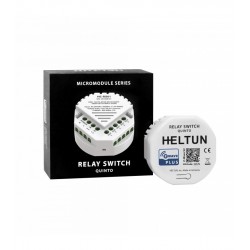
HELTUN - Módulo interruptor de fuerza 16A Z-Wave+ 700
HE-HLS01
Nuevo
El módulo de conmutación de alta potencia de Heltun es un dispositivo Z-Wave+ con funciones termostáticas. También es adecuado para luminarias o aparatos de hasta 16A.
Sin Stock
- Eliminar de mis favoritos
- Agregar este producto a mis favoritos
- Imprimir

Características técnicas
| Tecnología | Z-Wave Plus |
Descripción
TU COMODIDAD IMPORTA
¿Cuáles son los aspectos más importantes de su comodidad? ¿Es la temperatura ambiente general? ¿Control remoto o automático de aparatos, enchufes o grupos de luces? ¿O tal vez algo más? Cualquiera que sea la necesidad, HELTUN garantiza que se encargará de ello.
Toma el control
La avanzada tecnología de cruce de cero de HELTUN ofrece un aumento significativo de la longevidad y fiabilidad del sistema. El relé soporta una carga máxima de 16 amperios y es adecuado para controlar la calefacción eléctrica, así como las tomas de corriente, los aparatos o las luces.
Increíblemente pequeño e inteligente
El interruptor de servicio pesado con funciones de termostato aporta increíbles capacidades a cualquier aparato conectado. Hace que los enchufes eléctricos y las luces sean "inteligentes" con un control remoto avanzado, control y programabilidad. Ahora puede habilitar las funciones de termostato conectadas a Internet en los casos en que no se requieran la pantalla y los controles locales, como en el caso de los sistemas de descongelamiento de tejados o entradas, etc. Esto aporta la comodidad del control y la programación de las aplicaciones de los teléfonos inteligentes a los dispositivos "tontos" como enchufes y paneles eléctricos, calentadores de agua eléctricos, radiadores, chimeneas y sistemas de descongelación por suelo o radiante.
A 26 mm de profundidad, el módulo de conmutación también es increíblemente pequeño, encajando en cualquier caja de conexiones eléctricas rectangulares, redondas o cuadradas, incluso detrás de un dispositivo conectado.
Entradas, salidas y sensores
Puede conectar un sensor de temperatura NTC para monitorear las temperaturas ambientales o radiantes del sistema de piso/techo. Este sensor puede instalarse en la pared, bajo el suelo o en el techo, permitiendo medir con precisión las temperaturas de la superficie. El módulo de interruptores de alta resistencia HELTUN es totalmente compatible con los sensores NTC de otros fabricantes, por lo que no hay necesidad de reemplazar un sensor existente al instalarlo.
También puede controlar el módulo conectándolo a un sistema externo - como un sistema de alarma - utilizando un cable piloto que podría ser programado para reducir automáticamente la temperatura cuando la casa está vacía o encender los enchufes eléctricos/las luces cuando la gente llega a casa.
Conozca su consumo de energía
El sistema integrado de consumo de energía de HELTUN monitoriza con precisión la cantidad de energía que ha pasado a través de su módulo de conmutación de alta carga durante un día, semana o mes en particular. Con el módulo de conmutación, puede determinar la cantidad de energía utilizada por los principales aparatos, sistemas de entretenimiento, ordenadores, pequeños electrodomésticos o sistemas de iluminación completos.
Heltun también ha diseñado el circuito para que consuma casi cero vatios de potencia cuando está en modo de espera. Esto le ahorra energía y dinero incluso si su casa está equipada con muchos productos HELTUN.
Modos de termostato
Aunque el Módulo de Interruptores de Uso Intensivo no tiene pantalla ni botones, todas sus funciones de termostato son accesibles a través de un controlador de Onda Z. Aquí están los modos de termostato disponibles.
Los modos COM (Confort), ECO (Ahorro de energía) y VAC (Vacaciones) mantienen la temperatura que has especificado usando el controlador de Onda Z.
El modo SECO cambia a una temperatura más alta para calentar rápidamente para secar los pisos después de lavarlos. El modo DRY vuelve al modo anterior después del tiempo especificado.
El modo MAN (manual) le permite anular cualquier modo o programa actual y encender o apagar el calentador manualmente usando la interfaz de su controlador.
Consulte el manual del controlador para obtener instrucciones sobre cómo establecer los puntos de ajuste de la temperatura y los modos de los termostatos conectados.
Modo de tiempo: Termostato
Puedes reducir tu factura de electricidad y ayudar al medio ambiente simplemente usando el modo TIME a través de tu controlador Z-Wave. Ajuste el nivel de confort de su casa de acuerdo con los hábitos de su familia reduciendo la temperatura mientras todos están fuera y aumentándola por las tardes y las mañanas.
La gente pasa un promedio de 12 a 14 horas al día en casa. El resto del tiempo, una casa vacía necesita un mínimo de calefacción. Y como la mayor parte del tiempo en casa su familia duerme, puede marcar una gran diferencia al establecer el nivel de confort de su casa a 18°C por la noche, que se considera la temperatura óptima para dormir.
Usando el modo TIEMPO y su controlador, establezca diferentes temperaturas para la mañana, el día, la tarde o la noche. Por ejemplo: el modo "Mañana" puede comenzar a las 7:00 a.m. a 23°C y luego cambiar a "Día" a las 8:30 a.m. a 17°C cuando todos están en el trabajo y la escuela. El modo "Noche" puede comenzar a las 4:00 p.m. a 22 °C y luego cambiar a "Noche" a las 11:00 p.m. a 18 °C. Ajustar las temperaturas para estos cuatro períodos puede ahorrar mucho en su factura de electricidad, y puede ajustar los días de semana para los días de fin de semana.
Modo de tiempo: Otros dispositivos
El módulo de interruptores de alta resistencia puede conectarse a productos distintos de los controlados por un termostato, como paneles eléctricos, enchufes e iluminación. El modo de tiempo proporciona una capacidad extremadamente poderosa para programar ciclos de encendido y apagado para grupos de dispositivos conectados. Aquí hay algunas formas en las que el modo de tiempo puede agregar conveniencia, comodidad, seguridad y ahorros a su hogar:
Apagar los enchufes eléctricos conectados a los aparatos que consumen energía como lavadoras, secadoras y lavavajillas durante los períodos en que la electricidad es cara.
Apaga tu calentador de agua/caldera eléctrica en vacaciones o incluso por la noche y enciéndelo de nuevo por la mañana.
Apague los enchufes eléctricos cuando los miembros de la familia estén en el trabajo o de vacaciones para evitar que un incendio deje un aparato en funcionamiento (tetera, plancha, rizador de pelo, etc.).
Preprograme todas las luces de la casa y del patio para que se enciendan antes de que los visitantes lleguen a su casa de vacaciones.
Y al igual que con las funciones de termostato del módulo de conmutación de gran potencia, a través de un controlador se pueden asignar los aparatos conectados a ON u OFF durante los períodos de mañana, día, tarde o noche. Esto puede permitirle apagar fácilmente los enchufes conectados a las consolas de juegos por la noche o programar todas las luces exteriores para que se enciendan por la noche y por la mañana. Las posibilidades sólo están limitadas por la creatividad del usuario.
Poderosamente personalizable
Hay ocho modos diferentes que pueden seleccionarse para el módulo de interruptor de servicio pesado utilizando un cable piloto a otro dispositivo (por ejemplo, panel de alarma, interruptor de pared, etc.):
Estado de reversión - Si está encendido, apagado cuando el circuito está cerrado (o si está apagado, encendido).
Momentánea - Encendida cuando el circuito del cable piloto está cerrado, apagada cuando está abierto.
Reversa momentánea - Apagado cuando el circuito del cable piloto está abierto, encendido cuando está cerrado.
Sólo con interruptor - Cuando el circuito del cable piloto está cerrado (es decir, en cortocircuito).
Sólo apagar - Cuando el circuito del cable piloto está cerrado (es decir, en cortocircuito).
Cambiar el modo - Cambiar a un modo de termostato específico (preconfigurado en el menú de ajustes).
La salida de relé del Módulo de Interruptores de Servicio Pesado también puede ser controlada por un temporizador interno. Por ejemplo, después de encender el interruptor, se puede configurar para que se apague automáticamente más tarde (o viceversa: se encienda después de ser apagado).
Temporizador (ON y OFF) - Se enciende cuando el circuito del cable piloto se cierra, y luego se apaga después de un tiempo especificado.
Temporizador (APAGADO y ENCENDIDO) - Se apaga cuando el circuito del cable piloto se cierra, y se enciende después de un tiempo especificado.
Haz que tus interruptores sean increíblemente inteligentes
¿Tu carril DIN es un carril "estúpido"?
Dado que el Módulo de Interruptores de Uso Intensivo HELTUN puede manejar hasta 16 amperios, es un complemento perfecto para su panel de interruptores para monitorear y controlar grupos de dispositivos desde Internet a través de una puerta de enlace de Onda Z, como por ejemplo:
Las tomas de corriente conectadas a los principales dispositivos
Enchufes conectados a pequeños dispositivos con altas cargas
Grupos enteros de tomas de corriente
Grupos enteros de luces
El adaptador de montaje está disponible como accesorio para el módulo de interruptor de alta resistencia para adaptarse a los rieles DIN estándar (50 mm de ancho), o también se puede montar directamente en la pared con los tornillos y tacos suministrados.
Seguridad
El módulo de interruptores de alta resistencia puede mejorar la seguridad de su casa de varias maneras.
Sobrecarga - Si el Módulo de Interruptores de Uso Intensivo detecta demasiada energía de los aparatos conectados - como múltiples tomas eléctricas conectadas - se apagará automáticamente para protegerse de la sobrecarga del circuito. Esto es útil para muchas aplicaciones en las que se conectan múltiples cargas a un módulo de conmutación de cargas pesadas.
Sobrecalentamiento - El Módulo de Interruptor de Servicio Pesado también monitoriza continuamente la temperatura proporcionando múltiples capas de protección. Con un sensor NTC externo, monitoriza las temperaturas dentro de la caja de conexiones permitiendo la desconexión automática y la notificación al usuario si un enchufe se calienta demasiado. Incluso puede advertir al usuario del aumento de las temperaturas antes de alcanzar un nivel de apagado crítico, tras lo cual cerrará automáticamente la salida cuando cruce un umbral peligroso.
Retraso de carga alta - Si un miembro de la familia deja un aparato de alta energía encendido durante mucho tiempo - como una plancha conectada durante más de una hora - el Módulo de Interruptor de Carga Alta puede ser configurado para apagar automáticamente los enchufes conectados para evitar un incendio.
Los usuarios pueden establecer límites de apagado de carga alta, límites de tiempo y temperatura, y ajustes de notificación en los ajustes del módulo de interruptores de servicio pesado utilizando un controlador de onda Z.
Fácil de instalar
El módulo de interruptores de alta resistencia HELTUN puede instalarse fácilmente en cualquier caja de conexiones eléctricas estándar (rectangulares, cuadradas o redondas) en sólo unos minutos. La instalación sólo debe ser realizada por una persona capacitada en el manejo de sistemas eléctricos de alto voltaje.
Z-Wave Plus V2 certificado
Puedes conectar los dispositivos HELTUN a un controlador de automatización del hogar utilizando la última plataforma Z-Wave Plus V2 700. HELTUN cuenta con la avanzada tecnología Smart Start para una fácil integración del sistema y el marco de seguridad S2 con encriptación AES 256 para una transferencia de datos segura.
Este módulo de interruptor de gran potencia es compatible con todos los controladores y dispositivos certificados de Onda Z que implementan correctamente las clases de interruptores y termostatos de Onda Z. Con un controlador Z-Wave, puede gestionar todas las funciones del módulo de conmutación a través de una aplicación móvil, incluyendo los cambios de temperatura y de modo, la visualización de gráficos de consumo de energía y mucho más.
Se pueden conectar hasta 10 dispositivos separados al módulo de interruptores de alta resistencia HELTUN. Puedes combinarlo con cualquier interruptor de encendido y apagado compatible con la onda Z o cualquier otro interruptor para controlar diferentes sistemas de aire acondicionado en una habitación. Incluso puedes conectar detectores de movimiento y cambiar los modos de conmutación de alta carga cuando se detecta gente en la casa.
Las unidades HELTUN son compatibles con todas las frecuencias de Onda Z para diferentes países (Europa, Rusia, Israel, Australia, EE.UU., India, Hong Kong, China, Japón y Corea). La frecuencia correcta se puede seleccionar en el menú del dispositivo.
HELTUN lanza periódicamente un nuevo firmware para el dispositivo con características adicionales que pueden ser actualizadas remotamente a través de un proceso OTA (Over-The-Air) cifrado.
FUNCIONES:
Opciones de inclusión/exclusión en una red de Onda Z :
No está garantizado
S0 Seguro...
S2 no permitido, S2 permitido con llave
Control por asociación de 10 dispositivos de red
6 modos de funcionamiento: COM, ECO, VAC, SECO, TIEMPO, MANUAL
Cuatro programas: mañana, día, tarde y noche.
Programar y fijar la temperatura (calentadores)
Programación solamente (otros dispositivos)
Ocho modos de retransmisión (usando un cable piloto a otro dispositivo):
Invertir el estado
Momentánea
Invertir momentáneamente
Enciende sólo
Apagar sólo
Cambiar a
Temporizador (ON y OFF)
Temporizador (OFF y ON)
Tres modos de seguridad con notificación y apagado automático:
Sobrecarga (apagado automático en caso de sobrecarga)
Sobrecalentamiento (apagado automático en caso de sobrecalentamiento de la salida)
Retraso de carga alta (notificación y apagado automático cuando se supera el retraso de carga alta)
Puede ser usado con varios sensores NTC: Rango de valores de resistencia: 1kΩ - 100kΩ
Calibrando el sensor de temperatura
Rangos de ajuste de temperatura: 4 °C - 37 °C
Limitador de temperatura
Ajustar la histéresis de la temperatura
Medición de la temperatura: Centígrados (° C) o Fahrenheit (° F)
Reajustar el contador de consumo de energía
Botón de restablecimiento de fábrica
Actualizando el firmware de OTA (Over-The-Air)
DATOS TÉCNICOS:
Dimensiones: 50x50x26 mm
Material: Plástico retardante del fuego
Color: Blanco
Temperatura de funcionamiento: 0 °С a + 60 °С
Fuente de alimentación: 85-265VAC 50Hz / 60Hz, o 24-48VDC
Consumo de energía: <1 W
Carga resistiva máxima: 16А, 4000W @ 220V
Conmutación de relés con HELTUN Tecnología Avanzada de Paso Cero
Vida de los relés: 100.000 ciclos
Sensor externo de temperatura del suelo
NTC 10kΩ (incluido)
Rango de medición: -30 °C a + 80 °C
Precisión: ± 0,5 °C
Medidor de consumo de energía
Clase de IP: IP21
SDK Z-Wave Plus V2: V7.11
Módulo de Onda Z: ZGM130S
Ensamblado:
Caja de conexiones eléctricas: redonda, rectangular o cuadrada - profundidad mínima 40 mm.
Adaptador opcional para montaje en riel DIN (50 mm de ancho) o para atornillar en la pared
Información Ampliada Z-Wave (Inglés)
Descargue el manual desde aquí.
If successful, the LED indicator will blink white for two seconds then the device will reboot.
The factory reset will change all the Parameters to their original factory default values and will also Exclude the device from any Z-Wave network.
Note: Please use this procedure only when the network primary controller is missing or otherwise inoperable.
1. Ensure the HE-HLS01 is Powered On and the LED indicator blinks red slowly (i.e. it is excluded).
2. Start the Inclusion Mode from the gateway/controller.
3. To start the inclusion process on the HE-HLS01:
a) if you want to use the device as a “Binary Switch”, double-press the service button on the device (with no more than a one-second interval between presses).
b) if you want to use the device as a “Thermostat”, press four times the service button on the device (with no more than a one-second interval between presses).
4. The LED indicator will blink green quickly.
5. If the inclusion has been successful, the LED indicator will turn green for three seconds then continue slowly blinking green continuously while the HE-HLS01 is Powered On.
6. If the inclusion was not successful, the LED indicator will turn red for three seconds then continue slowly blinking red continuously while the HE-HLS01 is Powered On. In that case repeat the inclusion process (2-5) above.
Depending on the inclusion method it is possible also to use that as "Thermostat".
To start the inclusion process on the HE-HLS01:
a) if you want to use the device as a “Binary Switch”, double-press the service button on the device (with no more than a one-second interval between presses).
b) if you want to use the device as a “Thermostat”, press four times the service button on the device (with no more than a one-second interval between presses).
The altered capabilities are described in the corresponding sections in user manual:
Functions & Features
Device type “Binary Switch”
Device type “Thermostat”
Depending on the number of button presses (two or four) during the inclusion process HE-HLS01 could function as either “Binary Switch“ or “Thermostat“.
In case if the device is already included in Z-Wave network and there is a need to change the device type, it should be removed from network and re-included with the corresponding type.
1. Ensure the HE-HLS01 is Powered On and the LED indicator blinks green slowly (i.e. it is included in a Z-Wave network). 1. Start the Exclusion Mode from the gateway/controller.
2. To start the exclusion process on the HE-HLS01, double-press the service button on the device (with no more than a one-second interval between presses).
3. The LED indicator will blink red quickly.
4. If the exclusion has been successful, LED indicator will turn red for three seconds then continue slowly blinking red continuously while the HE-HLS01 is Powered On.
5. If the exclusion was not successful, the LED indicator will turn green for three seconds then continue slowly blinking green continuously while the HE-HLS01 is Powered On. In that case repeat the exclusion process (2-5) above.
Note: If the HE-HLS01 has previously been part of a Z-Wave network and not Excluded since, Inclusion is not possible without first performing an Exclusion or Factory Reset procedure.
Opiniones
30 otros productos de la misma categoría:
-
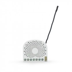
Bypass para...
-
Qubino...
-
Qubino...
-
Philio...
-
AEOTEC -...
-
AEOTEC -...
-
AEOTEC -...
-
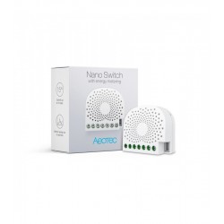
Aeotec Nano...
-
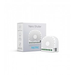
Aeotec Nano...
-
Qubino Mini...
-
WiDom Smart...
-
WiDom Smart...
-
WiDom Smart...
-
Qubino...
-
Fibaro...
-
Fibaro...
-
FIBARO RGBW...
-

FIBARO...
-
HELTUN -...
-
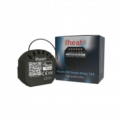
Heatit ZM...
-
Philio...
-
Philio...
-
Philio...
-
Controlador...
-
Heatit ZM...
-
Heatit ZM...
-
Shelly...
-
Shelly...
-
Shelly...
-
Shelly...