No products
Prices are tax included
Product successfully added to your shopping cart
There are 0 items in your cart. There is 1 item in your cart.


 View larger


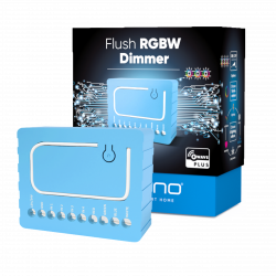
FIBARO RGBW Controller 2
FGRGBW-442
New
This RGB / RGBW controller can control LED strips, RGB / RGBW LEDs, and 12V or 24V light sources. It also allows you to do many other things in Z-Wave home automation
Out of stock
- Remove this product from my favorite's list.
- Add this product to my list of favorites.

Technical characteristics
| Technology | Z-Wave Plus |
| Characteristic | Dimmer |
More info
FIBARO RGBW Controller 2 is a universal controller compatible with Z-Wave Plus.
RGB / RGBW controller.
The FIBARO RGBW Controller 2 uses the PWM output signal, allowing you to
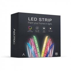
LED strips, RGB, RGBW, halogen lights and other resistive lights.
loads. It can also measure the active power and energy consumed by the
load. The controlled devices can be powered by 12 or 24V DC.
The inputs support momentary / toggle switches and 0-10V analog sensors, such as temperature sensors, humidity sensors, light sensors, etc.
Unleash your fantasy and express your mood with colored light! With the Fibaro RGBW Controller 2 you paint your bathroom with light using LED stripes, adjusted to the temperature of the water in your bathtub. Or have your house light turn red as soon as an alarm sensor is activated. There are 3 million colors at your disposal. So the only limit is your imagination.
Thanks to the compact radio module, you can integrate the connected RGB and RGBW LED lights into your Z-Wave network. With the remote control, smartphone or sensor-controlled automation you can switch and dim the LEDs and select any color value.
Characteristics:
Radio module for the installation of wall boxes
RGBW color select switch, attenuator and function
Energy measurement function
Voltage: 12V or 24V DC
Max. Output: 6 single channel, 12 to all output channels in total
Power consumption: <0.3 W
Up to 4 analog sensors (0-10 V) can be connected (sensors not included in delivery)
Wireless technology: Z-Wave Plus
Security: S2
SmartStart enabled
Dimension: 42 x 38 x 18mm
Extended Z-Wave info
Manual download HERE.
1. Power the device.
2. Set the main controller in (Security/non-Security Mode) add mode (see the controller’s manual).
3. Quickly, three times click the button.
4. If you are adding in Security S2 Authenticated, scan the DSK QR code or input the underlined part of the DSK (on the device label).
5. LED will start blinking yellow, wait for the adding process to end.
6. Successful adding will be confirmed by the Z-Wave controller’s message.
To add the device to the Z-Wave network using SmartStart:
1. Set the main controller in Security S2 Authenticated add mode (see the controller’s manual).
2. Scan the DSK QR code or input the underlined part of the DSK (on the device label).
3. Power the device.
4. LED will start blinking yellow, wait for the adding process to end.
5. Successful adding will be confirmed by the Z-Wave controller’s message
1. Power the device.
2. Set the main controller into remove mode (see the controller’s manual).
3. Quickly, three times click the button.
4. LED will start blinking yellow, wait for the removing process to end.
5. Successful removing will be confirmed by the Z-Wave controller’s message.
1. Press and hold the button to enter the menu.
2. Release the button when the device glows yellow.
3. Quickly click the button to confirm.
4. After a few seconds the device will be restarted, which is signaled with the red LED colour.
Use re- set procedure only if the primary controller is missing or inoperable.
Reviews
Funciona estupendo
Conectado con el Fibaro HC3 y todo estupendo. Aún le falta la misma integración que tenía en el HC2, pero funciona muy bien.