
No products
Prices are tax included
Product successfully added to your shopping cart
There are 0 items in your cart. There is 1 item in your cart.
Viewed products
-

HELTUN - Quinto...
The HELTUN Quinto switch module is a...
-

Heatit Z-TRM3 Z-Wave...
Heatit Z-TRM3 is an electronic Z-Wave...
-

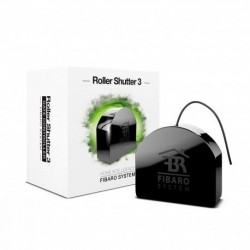
FIBARO Roller Shutter 3
The Fibaro Roller Shutter 3 FGR-223...
-

ZIPATO - Sensor de Gas...
Philio's Z-Wave Plus Panic Button is...
-

AJAX SpaceControl...
One knob to control security modes....


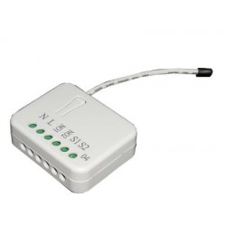
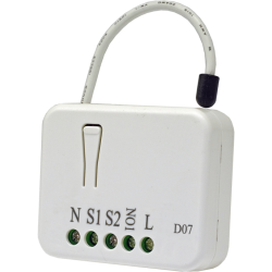
HELTUN - Quinto 5-channel switch module Z-Wave + 700
HE-RS01
New
The HELTUN Quinto switch module is a multiple relay with five dry contact outputs. It can control any type of load up to 5A per output.
Out of stock
- Remove this product from my favorite's list.
- Add this product to my list of favorites.

Technical characteristics
| Technology | Z-Wave Plus |
More info
YOUR COMFORT MATTERS.
When you consider your comfort at home, what is the most important? Can you turn the lights on or off without going through different rooms? Or being able to close the door, close the blinds, and dim the lights with one touch? Or maybe something else? Whatever you need, HELTUN has you covered.
Take control
Five dry-contact relays that carry a load of 5 amps each. HELTUN's advanced zero-crossing technology offers a significant increase in longevity and reliability. Control the lighting or any device: door, gate, shutter, motorized valve, ...
Incredibly small and smart
The fifth switch module with shutter control offers incredible capabilities to any connected device. Makes light switches "smart" with advanced remote monitoring, control, and programmability. This brings the convenience of controlling and automating smartphone applications to "dumb" devices such as light switches, electronic door locks, electric gates, shutters, windows, and valves.
For example, you can control up to ...
Five on and off devices
Three on / off devices and a bi-directional motor
One on / off device and two bi-directional motors
At 26mm deep, the 5th's switch module is also "incredibly small", fitting into any rectangular, round or square electrical junction box, even behind connected devices.
Inputs and outputs
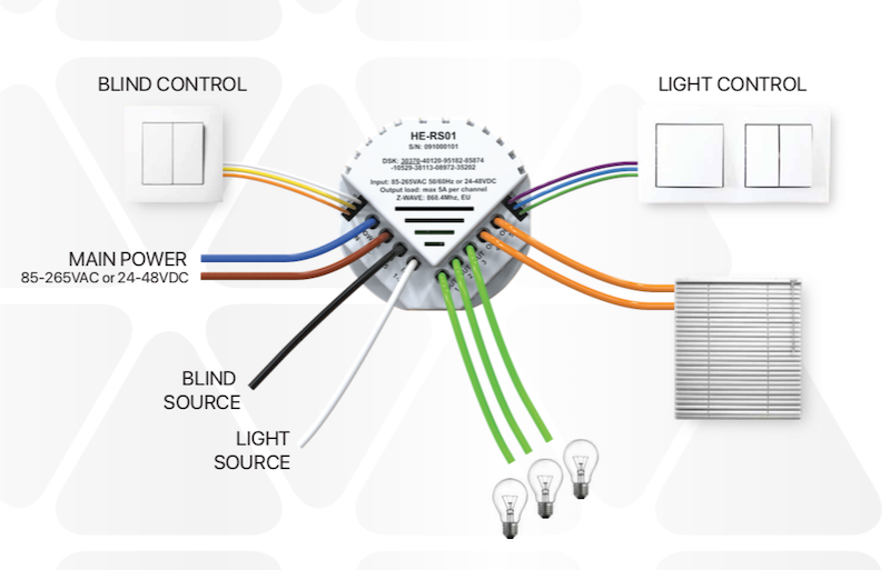
The main power input can be 85-265VAC or 12-48VDC. The fifth switch module has five relay outputs with a maximum load of 5 amps each.
It also has two independent inputs for the relay channels that allow controlling systems with different energy sources or using the outputs as dry contacts: for example, to turn 220VAC lights on or off and to control motorized valves with 24VDC power.
It also has six pilot wire inputs: one common and five for each transmission channel. This allows the fifth switch module to be controlled by up to five different sources (for example, five different light switches) and to control all relay outputs separately.
Each transmission channel uses advanced HELTUN technology to provide a significant increase in longevity and reliability.
Know your energy consumption
The integrated energy consumption system accurately monitors the amount of energy you have used over the course of a day, a week or a month. Do your current light switches do this?
Simply specify the load consumption in watts for each relay channel and the logic in the fifth switch module will calculate the total consumption based on the time since the output was in the "ON" state.
Heltun has also designed the circuit to draw almost zero watts of power when in standby mode. This saves energy and money, especially if your home is equipped with many HELTUN products.
Make your switches incredibly smart
Is your DIN rail a "stupid" rail?
As HELTUN's switch module has 5 channels each capable of handling up to 5 amps, it is a perfect complement to your switch panel for monitoring and controlling groups of devices from the Internet through a Z-Wave gateway, such as per example:
Whole groups of lights
Motorized valves
Door locks
Motorized awnings, gates and gates
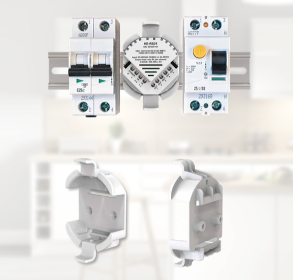
The module mounting adapter is available as an accessory to fit standard DIN rails (50mm), or it can also be mounted directly to the wall using the supplied screws and plugs.
Powerfully customizable
There are seven different selectable modes for the 5th switch module with up to five pilot wires used to control any relay output of devices such as a wall switch, an alarm panel, etc.
Reverse State - If on, turns off when pilot wire circuit closes (or if off, turns on).
Momentary - Lights when the pilot wire circuit is closed, turns off when the pilot wire circuit is open.
Momentary Reverse - Turns off when pilot wire circuit is open, turns on when closed.
On Only - When the pilot wire circuit is closed (ie shorted).
Off Only - When the pilot wire circuit is closed (i.e. shorted).
The output of the fifth switch module can also be controlled by an internal timer. For example, after the switch is turned on, it can be set to automatically turn off later (or vice versa: it turns on after being turned off).
This function can be used to open or close garage doors, gates, blinds, curtains, locks, etc., and then return them to their previous state without the need for further inputs.
Timer (ON and OFF) - Lights when the pilot wire circuit closes, then turns off after a specified time.
Timer (OFF and ON) - Turns off when the pilot wire circuit closes, and turns on after a specified time.
Control of motorized devices
The HELTUN switch module does more than control your home lighting. You can use it to control motorized blinds, curtains, garage doors, entry doors, and electric locks. You have full control over the programming of the different buttons for specific functions.
For example, you can designate the upper left button to raise the blinds in the living room and the lower left button to lower them. In this mode, if the blinds are raised and then the down button is pressed, the system automatically cancels the UP command and initiates a DOWN command, or vice versa.
The system also calculates the position of the blinds when they are fully open or closed and automatically stops the motor when it reaches the upper or lower limit.
Programming and scenarios
Using the internal timer of the HELTUN 5th switch module, you can create a schedule for certain devices. For example:
Open the blinds at 7:00 am and close them at 10:00 pm
Turn on the porch light at 7:00 pm and turn it off at 1:00 am
The possibilities for adding convenience and comfort are endless and are only limited by the creativity of the owner or installer of the HELTUN 5th switch module.
Easy to install
The fifth switch module can easily be installed in any standard electrical junction box (square or round). Installation should only be carried out by a person trained in handling high voltage electrical systems.
Z-Wave Plus V2 certified
You can connect HELTUN devices to a home automation controller using the latest Z-Wave Plus V2 700 platform. HELTUN features advanced Smart Start technology for easy system integration and the S2 security framework with AES 256 encryption for seamless handover. secure data.
The HELTUN switch module is compatible with all Z-Wave certified controllers and devices that correctly implement the Z-Wave touch switch control classes. With a Z-Wave controller, you can manage all switch functions through a mobile app, including temperature changes, displaying power consumption graphs, and more.
Up to 50 separate devices can be connected to the HELTUN switch module. You can combine it with any Z-Wave compatible on / off switch or other tactile switch to control different systems in a room.
HELTUN devices are compatible with all Z-Wave frequencies for different countries (Europe, Russia, Israel, Australia, USA, India, Hong Kong, China, Japan and Korea). The correct frequency can be selected in the device menu.
HELTUN periodically releases new firmware for the device with additional features that can be remotely updated through an encrypted OTA (Over-The-Air) process.
FUNCTIONS:
Z-Wave network inclusion / exclusion options
It is not guaranted
S0 Safe ...
S2 not allowed, S2 allowed with key
Association control with 50 network devices
Control of motorized devices (blind mode)
Each of the 5 pilot wire inputs can control any of the 5 relay outputs.
Up to 5 outputs can be controlled by a pilot wire
Seven modes for each output:
Turn on only
Disable only
Invert state (ON to OFF or OFF to ON)
Momentary (ON when shorted, OFF when released)
Inverted momentary (OFF when shorted, ON when released)
Timer (ON and OFF after specified time)
Timer (OFF and ON after specified time)
Each relay output can be managed by a Z-Wave gateway or a partner device.
Each pilot wire can trigger scenes
Programming mode
Power Consumption Software Logic
Factory reset button
SmartStart technology for quick addition to Z-Wave networks
OTA (Over-The-Air) Encrypted Firmware Update
TECHNICAL DATA:
Dimensions: 50x50x26 mm
Material: Fire retardant plastic
White color
Five relays for resistive loads up to 5A each
Two independent relay inputs (dry contact)
Relay switching with HELTUN Advanced Zero Pass Technology
Relay life: 100,000 cycles
One common wire (S) and five pilot wires (S1, S2, S3, S4, S5) for external control
Power Consumption Software Logic
Power supply: 85-265VAC 50Hz / 60Hz, or 24-48VDC
Power Consumption: <1W
Operating temperature: 0 °! at + 60 °!
IP class: IP21
Z-Wave Plus V2 SDK: V7.11
Z-Wave Module: ZGM130S
Assembly:
Electrical connection box: round or square, minimum depth 40 mm.
Optional adapter for DIN rails (50mm wide) or wall mount
Extended Z-Wave info
Manual download HERE.
1. Ensure the HE-RS01 is Powered On and the LED indicator blinks red slowly (i.e. it is excluded)
2. Start the inclusion mode from the gateway / controller
3. To start the inclusion process on the HE-RS01, double-press the service button on the device (with no more than a one-second interval between presses).
4. The LED indicator will blink green quickly.
5. If the inclusion has been successful, the LED indicator will turn green for three seconds then continue slowly blinking green continuously while the HE-RS01 is Powered On.
6. If the inclusion was not successful, the LED indicator will turn red for three seconds then continue slowly blinking red continuously while Powered On. In that case repeat the inclusion process (2-5) above.
1. Ensure the HE-RS01 is Powered On and the LED indicator is slowly blinking green (i.e. it is included in a Z-Wave network).
2. Start the exclusion mode from the gateway/controller.
3. To start the exclusion process on the HE-RS01, double-press the service button on the device (with no more than a one-second interval between presses).
4. The LED indicator will blink red quickly.
5. If the inclusion has been successful, the LED indicator will turn red for three seconds then continue blinking red slowly continuously while the HE-RS01 is Powered On.
6. If the inclusion was not successful, the LED indicator will turn green for three seconds then continue slow blink green all the time the device is Powered On. In that case repeat the exclusion process (2-5) above.
Note: If the HE-RS01 has previously been part of a Z-Wave network and has not been excluded since (the LED indicator will blink green slowly). Inclusion is not possible without first performing an Exclusion or Factory Reset procedure.
NOTE: This factory reset procedure will change all parameters to the original factory default values and will also exclude the device from any associated Z-Wave network.
Reviews
30 other products in the same category:
-
Qubino...
-
Philio...
-
AEOTEC -...
-
AEOTEC -...
-
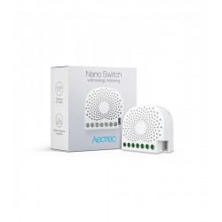
Aeotec...
-
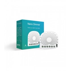
Aeotec Nano...
-
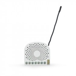
Aeotec Nano...
-
Qubino Mini...
-
WiDom Smart...
-
WiDom Smart...
-
WiDom Smart...
-

Qubino...
-
Fibaro...
-
Micromodule...
-
FIBARO RGBW...
-
FIBARO...
-
HELTUN -...
-
Heatit ZM...
-
Philio...
-

ZOOZ...
-
Philio...
-
Philio...
-
Z-Wave to...
-
Heatit ZM...
-
Heatit ZM...
-

Shelly...
-
Shelly...
-

Shelly...
-
Shelly...
-

FIBARO...