No products
Prices are tax included
Product successfully added to your shopping cart
There are 0 items in your cart. There is 1 item in your cart.


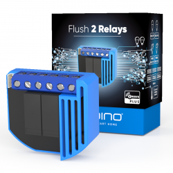
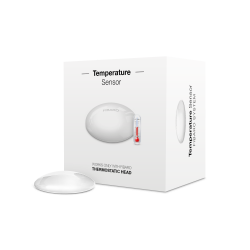
Qubino Flush On / Off Thermostat 2 - Z-Wave + thermostat micromodule
ZMNKID1
New
Z-Wave Plus technology smart thermostat that also measures energy consumption. Built-in / concealed format for mechanism box or surface box. It has a probe. Supports loads up to 16 amps.
In Stock
- Remove this product from my favorite's list.
- Add this product to my list of favorites.

Technical characteristics
| Technology | Z-Wave Plus |
| Characteristic | Consumption Measurement |
More info
The Qubino Thermostat On / Off 2 thermostat is a Z-Wave wireless technology thermostat in micromodule format and is ideal for remote control of electric or underfloor heating systems based on hot water circuits (the most common in Spain), electric water heaters, hot water pumps, electric radiators and the like. It connects directly to a 240 V AC power supply or a 24 V DC source and does not require batteries.
Measure the energy consumption of your electric heating system
The smart thermostat measures the energy consumption of the connected heating system: energy consumption in W and accumulated consumption in kWh. (This is generally useful if the source of heat generation is electrical).
Automatically measure and regulate temperature
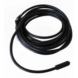
The Qubino Thermostat On / Off 2 smart thermostat comes with a digital temperature sensor. It allows to measure and control the ambient temperature by automatically connecting and disconnecting the connected heat source.
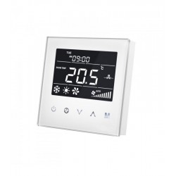
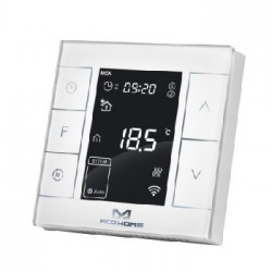
You can decide if you want to display the temperature in ° C or ° F on your Z-Wave home automation controller. (Fibaro, eedomus, smartthings, Vera, Home Assistant, OpenHAB, etc.)
The Qubino Flush On / Off 2 thermostat can be used with all types of heating systems directly or indirectly.
The Qubino Flush On / Off 2 thermostat works with gas and gas-oil heating boilers (generally by inserting a potential-free relay), heat pump, electric radiators, electric underfloor heating, underfloor heating using hot water circuits , infra-red panels ...
Advantages of Qubino Flush On / Off Thermostat 2 - Z-Wave + thermostat micromodule
It is a wireless and smart home device that is used as a heating or hot water controller and also measures energy consumption.
It is ideal for wireless control of electric or water underfloor heating systems, electric water heaters, hot water pumps, electric radiators, IR panels, etc. Allows you to set schedules to adjust the temperature of your home to your lifestyle. Automatically turns off your smart heating system after you go out in the morning and turns it back on remotely before heading home.
Connected to a temperature sensor, it causes the heating system to turn on from time to time to prevent the temperature from dropping, say, below 17 ° C. Your home will always welcome you with an optimal temperature, no matter how long you are going to be away.
In a typical house located in the northern hemisphere, heating accounts for about half of the total energy consumption.
The Qubino Flush On / Off Thermostat 2 can significantly reduce energy needs and save money on heating by keeping your home at an optimal temperature. Heating each room separately offers a maximum level of well-being while making your home more energy efficient. The Qubino Flush On / Off Thermostat 2 smart thermostat enables smart zoning, which means you can independently turn off heating in rooms and save heat and energy without compromising comfort.
The Qubino Flush On / Off Thermostat 2 allows you to set a different temperature in each room based on your needs. Creating smart zones throughout your home will reduce the energy consumption of your heating system by reducing the temperature in empty rooms. At the same time, you can create a perfect climate where and when it is needed.
Being able to turn off major energy consumers like heating systems while you are away will dramatically lower your electricity bills. But not at the cost of your comfort.
How does Qubino Flush On / Off Thermostat 2 work ?
Qubino wireless devices for smarthome are developed with the world-renowned technology for smart homes: Z-Wave. This means that Qubino devices connect to a smart home hub (gateway or home automation center) that also works with Z-Wave technology. Through the application of the home automation center, we can add the Qubino devices to the smart home network and control them with the smartphone or set schedules that automatically activate or deactivate the devices, that the thermostats trip when there is presence or turn off the heating when there is none , etc..
How do you install?
Qubino devices communicate via wireless protocol, so there is no need to tear down walls or install additional cables in your electrical network. Installation is quick and easy.
Connect the Qubino device behind your existing wall switch, next to the electric heating valves, near the water pump - where you need it, (see the electrical schematic for connection diagrams), pair it with a Z- gangway Wave and control your device with a smartphone or set scenarios to work automatically.
Check the installation videos to see different application examples of this thermostat:
Installation of Qubino Flush On / Off Thermostat 2 for underfloor heating :
Installation of Qubino Flush On / Off Thermostat 2 for heating by means of a hot water heater / tank (less popular in Spain and Portugal)
Installation of Qubino Flush On / Off Thermostat 2 for heating with infrared panels or electric radiators :
Installation of Qubino Flush On / Off Thermostat 2 to control the heating water circulation pump and / or radiators:
For quick and hassle-free setup, Qubino Thermostat 2 is compatible with Z-Wave SmartStart. The Qubino Smart Thermostat setup is easy for everyone to use. Just scan the device's QR code, install it, and power it up. The SmartStart gateway recognizes the device and enrollment is done automatically.
FUNCTIONS:
Remote control (via smartphone, tablet or PC) and on / off of local valves for underfloor heating systems with water, or underfloor heating and electric resistance, electric water heaters, hot water pumps, radiators electric, night rate accumulators and the like.
Operates with a push button (momentary switch) and a toggle switch
Able to measure the power consumption of the connected device in real time through a smartphone
Works on 110-240 VAC or 24-30 VDC
One of the easiest and fastest installations of this type of equipment; it can be integrated into even the smallest flush-mounted or junction boxes.
Saves and restores the last state after a power outage.
The range of the digital temperature sensor is between -25 and +80 ° C.
Supports the inclusion of SmartStart for quick installation
Automatically turns the device on and off according to the hysteresis.
Automatically turns on the unit if the temperature is too low (antifreeze).
Supports additional settings for expert users, allowing advanced configuration
It acts as a signal repeater that improves the range and stability of your Z-Wave network.
Can be used to remotely control and trigger other devices on your Z-Wave network
TECHNICAL SPECIFICATIONS
Power supply: 110 - 240 VAC ± 10% 50 / 60Hz, (24-30VDC)
Rated load current of AC / DC output (resistive load): 1 X 10 A (230 V AC) / 1 X 10 A / 30 V DC
AC / DC output circuit power (resistive load): 2300W (230VAC) / 240W (24VDC)
Power measurement accuracy: P = 5-50W, +/- 3W P> 50W, +/- 3%.
Operating temperature: -10 ~ + 40 ° C
Z-wave operating range: up to 40m indoors
Dimensions (WxHxD) (with packaging): 41.8x36.8x16.9 mm (115x96x22 mm)
Weight (with packaging): 48 g (64 g)
Power Consumption: 0.4W
For installation in boxes: Ø e 60 mm or 2M
Switching: relay
Digital temperature sensor cable length: 1000mm
Z-Wave repeater: Yes
![]()
Why Qubino?
Qubino products are designed and manufactured in the EU and contain only the highest quality components.
Qubino is the trademark of GOAP. The GOAP company has more than 30 years of experience in automation projects and a history of success in the implementation of automation systems in 50% of the largest and most luxurious cruise ships on the planet.
Innovation is our core value and it is ingrained in everything we do. We strive to constantly improve and introduce new features, ahead of the times. Some of our products are unique in the world. To constantly bring new ideas to life, we collaborate with universities and research centers.
Qubino guarantees 100% the quality of the devices. Such high quality can be offered because every Qubino product goes through rigorous quality control standards throughout the entire production process. Each device receives a unique serial number and part number, only after going through a strict testing procedure.
To ensure the quality of the products, before they enter the market, we test and certify them with independent certification institutions to receive international recognition.
Qubino products comply with EU directives, to guarantee the highest safety standards.
Our customer service policy advises that each customer receives a response within 24 hours.
Just go to our support website and open a new support ticket. By providing us with the unique serial number and part number of the product, we will automatically review the production log file that contains the device information and parameters. This allows us to immediately identify and resolve problems, offering you the best customer support.
Extended Z-Wave info
Manual download HERE.
DSK access via UI
Gateways, which implement the S2 and Smart Start security feature, display an input dialog box, with a full or partial DSK key. The majority of them display a partial DSK (they don't show the PIN code), when the device is included with the S2-Authenticated security scheme. When included with the S2-Unauthenticated, some gateways show the complete DSK while others perform the complete inclusion process without prompting the user with the dialogue.
1. Scan QR code on device label and add S2 DSK to Provisioning List in gateway (hub)
2. Connect the device to the power supply (with the temperature sensor already connected).
3. Inclusion will be initiated automatically within few seconds of connection to the power supply and the device will automatically enrol in your network (when the device is excluded and connected to the power supply it automatically enters the LEARN MODE state).
NOTE: LEARN MODE state allows the device to receive network information from the controller.
ⓘ SmartStart inclusion is a part of S2 security level, so if you want to use SmartStart, you need to include it as S2 Authenticated.
MANUALLY ADDING THE DEVICE TO A Z-WAVE NETWORK (MANUAL INCLUSION)
1. Enable add/remove mode on your Z-Wave gateway (hub)
2. Connect the device to the power supply (with the temperature sensor already connected*)
3. Toggle the switch connected to the I1 terminal 3 times within 3 seconds (The device has to get On/Off signal 3 times, meaning 3 times click on the push button or with the normal button 3 times On/Off.) (this procedure puts the device in LEARN MODE) in the first minute after power cycle.
OR
If the device is powered by 24 V SELV supply, press and hold the S (Service) button between 3 and 6 seconds (this procedure puts the device in LEARN MODE)
4. A new device will appear on your dashboard
5. Inclusion with the switch connected to I1 terminal is not limited by time
*If connecting the temperature sensor, switch off the power supply.
NOTE1: LEARN MODE state allows the device to receive network information from the controller.
1. Connect the device to the power supply
2. Make sure the device is within direct range of your Z-Wave gateway (hub) or use a hand-held Z-Wave remote to perform exclusion
3. Enable add/remove mode on your Z-Wave gateway (hub)
4. Toggle the switch connected to the I1 terminal 3 times within 3 seconds in the first minute after power cycle (The device has to get On/Off signal 3 times, meaning 3 times click on the push button or with the normal button 3 times On/Off).
OR
If the device is powered by 24 V SELV supply, press and hold the S (Service) button between 3 and 6 seconds
5. Exclusion with the switch connected to I1 terminal is not limited by time
6. The device will be removed from your network, but any custom configuration parameters will not be erased
NOTE1: LEARN MODE state allows the device to receive network information from the controller.
NOTE2: After device is excluded you should wait 30 seconds before performing re-inclusion.
1. Connect the device to the power supply
2. Within the first minute (60 seconds) the device is connected to the power supply, toggle the switch connected to the I1 terminal 5 times within 3 seconds (The device has to get On/Off signal 5 times, meaning 5 times click on the push button or with the normal button 5 times On/Off).
OR
If the device is powered by 24 V SELV supply, press and hold the S (Service) button for more than 6 seconds
ⓘBy resetting the device, all custom parameters previously set on the device will return to their default values, and the owner node ID will be deleted. Use this reset procedure only when the main gateway (hub) is missing or otherwise inoperable. If an end device is factory reset, it is reverted to the Z-Wave SmartStart inclusion state.
Reviews
Accessories
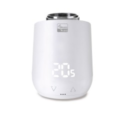
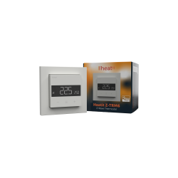
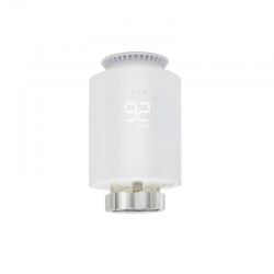
30 other products in the same category:
-

MCO Home -...
-
MCO HOME -...
-

MCO HOME -...
-
Fibaro -...
-
Fibaro -...
-
Fibaro...
-
MCO Home -...
-
MCO Home -...
-
REMOTEC -...
-
MCO HOME -...
-
MCO HOME -...
-
SECURE...
-
Heatit...
-
Heatit...
-
MCO-Home...
-

HELTUN...
-
HELTUN...
-
MCO Home -...
-
Airzone...
-
Heatit...
-
MCO Home IR...
-
Remotec...
-
Eurotronic...
-
Heatit...
-
ZVIDAR...
-
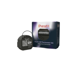
Heatit ZM...
-
Z-Wave...
-
Heatit...
-

MCO Home...
-

MCO MH5-WH...