Sem produtos
Preços com IVA
Produto adicionado com sucesso ao seu carrinho de compras
Existem 0 produtos no seu carrinho de compras. Existe um produto no seu carrinho de compras.


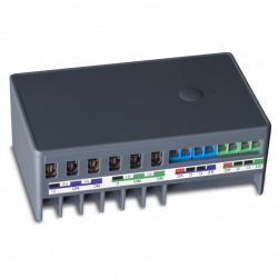
HELTUN - módulo de chave de força 16A Z-Wave + 700
HE-HLS01
Novo
O módulo de chave de alta potência de Heltun é um dispositivo Z-Wave + com funções termostáticas. Também é adequado para luminárias ou acessórios de até 16A.
Não disponível
- Retirar este produto da minha lista de favoritos.
- Adicionar este produto à minha lista de favoritos.

Características tecnicas
| Tecnologia | Z-Wave Plus |
Mais Informação
SEU CONFORTO É IMPORTANTE.
Quais são os aspectos mais importantes do seu conforto? É a temperatura ambiente geral? Controle remoto ou automático de aparelhos, tomadas ou grupos de luzes? Ou talvez outra coisa? Seja qual for a necessidade, a HELTUN garante que cuidará de tudo.
Assumir o controle
A avançada tecnologia zero-crossing da HELTUN oferece um aumento significativo na longevidade e confiabilidade do sistema. O relé suporta uma carga máxima de 16 amperes e é adequado para controlar o aquecimento elétrico, bem como tomadas elétricas, aparelhos ou luzes.
Incrivelmente pequeno e inteligente
O switch de serviço pesado com funções de termostato traz recursos incríveis para qualquer aparelho conectado. Torna as tomadas e luzes elétricas "inteligentes" com controle remoto avançado, controle e programabilidade. Agora você pode habilitar as funções do termostato conectado à Internet nos casos em que a tela e os controles locais não são necessários, como sistemas de degelo no telhado ou na garagem, etc. Isso traz a conveniência de controle e programação de aplicativos de smartphones para dispositivos "burros", como tomadas e painéis elétricos, aquecedores elétricos de água, radiadores, lareiras e sistemas de descongelamento sob o piso ou sob o piso.
Com 26 mm de profundidade, o módulo de chave também é incrivelmente pequeno, cabendo em qualquer caixa de junção elétrica retangular, redonda ou quadrada, mesmo atrás de um dispositivo conectado.
Entradas, saídas e sensores
Você pode conectar um sensor de temperatura NTC para monitorar a temperatura ambiente ou radiante do sistema de piso / teto. Este sensor pode ser instalado na parede, sob o piso ou no teto, permitindo medir com precisão as temperaturas da superfície. O Módulo de Chave de Trabalho Pesado HELTUN é totalmente compatível com sensores NTC de terceiros, portanto, não há necessidade de substituir um sensor existente durante a instalação.
Você também pode controlar o módulo conectando-o a um sistema externo - como um sistema de alarme - usando um fio piloto que pode ser programado para diminuir automaticamente a temperatura quando a casa estiver vazia ou ligar as tomadas / luzes quando as pessoas voltarem.
Conheça o seu consumo de energia
O sistema integrado de consumo de energia da HELTUN monitora com precisão a quantidade de energia que passou por seu módulo de chave de alta carga durante um determinado dia, semana ou mês. Com o módulo de chave, você pode determinar a quantidade de energia usada pelos principais aparelhos, sistemas de entretenimento, computadores, pequenos aparelhos ou sistemas completos de iluminação.
Heltun também projetou o circuito para consumir quase zero watts de energia quando em modo de espera. Isso economiza energia e dinheiro, mesmo se sua casa estiver equipada com muitos produtos HELTUN.
Modos de termostato
Embora o Heavy Duty Switch Module não tenha visor ou botões, todas as suas funções de termostato são acessíveis por meio de um controlador Z-Wave. Aqui estão os modos de termostato disponíveis.
Os modos COM (Conforto), ECO (Economia de energia) e VAC (Férias) mantêm a temperatura que você especificou usando o controlador Z-Wave.
O modo DRY muda para uma temperatura mais alta para aquecer rapidamente para pisos secos após a lavagem. O modo DRY retorna ao modo anterior após o tempo especificado.
O modo MAN (manual) permite que você substitua qualquer modo ou programa atual e ligue ou desligue manualmente o aquecedor usando a interface do controlador.
Consulte o manual do controlador para obter instruções sobre como definir os pontos de ajuste de temperatura e os modos dos termostatos conectados.
Modo de tempo: termostato
Você pode reduzir sua conta de eletricidade e ajudar o meio ambiente simplesmente usando o modo TIME através do controlador Z-Wave. Ajuste o nível de conforto da sua casa de acordo com os hábitos da sua família, baixando a temperatura enquanto todos estão fora e aumentando-a à noite e pela manhã.
As pessoas passam em média de 12 a 14 horas por dia em casa. No resto do tempo, uma casa vazia precisa de aquecimento mínimo. E como sua família dorme a maior parte do tempo em casa, você pode fazer uma grande diferença ajustando o nível de conforto de sua casa para 18 ° C à noite, que é considerada a temperatura ideal para dormir.
Usando o modo TIME e seu controlador, defina diferentes temperaturas para manhã, dia, tarde ou noite. Por exemplo: o modo "Manhã" pode começar às 7h00 a 23 ° C e depois mudar para o "Dia" às 8h30 a 17 ° C quando todos estiverem no trabalho e na escola. O modo "Noite" pode começar às 16h00 a 22 ° C e depois mudar para "Noite" às 23h00 a 18 ° C. Ajustar as temperaturas para esses quatro períodos pode economizar muito na conta de luz, e você pode ajustar os dias da semana para os dias de fim de semana.
Modo de tempo: outros dispositivos
O módulo de chave de serviço pesado pode ser conectado a produtos diferentes daqueles controlados por um termostato, como painéis elétricos, tomadas e iluminação. O modo horário fornece uma capacidade extremamente poderosa de agendar ciclos de ativação e desativação para grupos de dispositivos conectados. Aqui estão algumas maneiras como o Modo hora pode adicionar conveniência, conforto, segurança e economia à sua casa:
Desligue as tomadas elétricas conectadas a aparelhos que consomem energia, como lavadoras, secadoras e lava-louças, durante os períodos em que a eletricidade é cara.
Desligue o aquecedor elétrico de água / caldeira nas férias ou mesmo à noite e ligue-o novamente pela manhã.
Desligue as tomadas elétricas quando os familiares estiverem no trabalho ou de férias para evitar que um incêndio deixe um aparelho ligado (chaleira, ferro, chapinha, etc.).
Pré-programe todas as luzes da casa e do pátio para acender antes que os visitantes cheguem à sua casa de férias.
E, como acontece com as funções de termostato do módulo de chave de alta potência, um controlador pode atribuir aparelhos conectados a LIGAR ou DESLIGAR durante os períodos da manhã, dia, tarde ou noite. Isso pode permitir que você desligue facilmente os plugues conectados aos consoles de jogos à noite ou programe todas as luzes externas para acenderem à noite e pela manhã. As possibilidades são limitadas apenas pela criatividade do usuário.
Poderosamente personalizável
Existem oito modos diferentes que podem ser selecionados para o módulo de chave de serviço pesado usando um fio piloto para outro dispositivo (por exemplo, painel de alarme, interruptor de parede, etc.):
Reverter estado - Se ligado, desligado quando o circuito é fechado (ou se desligado, ligado).
Momentâneo - Ligado quando o circuito do fio piloto está fechado, desligado quando aberto.
Momentary Reverse - Desligado quando o circuito do fio piloto está aberto, ligado quando fechado.
Switch Only - Quando o circuito do fio piloto está fechado (ou seja, em curto).
Apenas desligamento - quando o circuito do fio piloto está fechado (ou seja, em curto).
Alterar modo - Muda para um modo de termostato específico (predefinido no menu de configurações).
A saída de relé do Módulo de Chave Pesada também pode ser controlada por um temporizador interno. Por exemplo, após ligar a chave, ela pode ser configurada para desligar automaticamente mais tarde (ou vice-versa: ligar depois de ser desligada).
Temporizador (LIGADO e DESLIGADO) - Acende quando o circuito do fio piloto fecha e desliga após um tempo especificado.
Temporizador (DESLIGADO e LIGADO) - Desliga quando o circuito do fio piloto fecha e liga após um tempo especificado.
Torne seus interruptores incrivelmente inteligentes
O seu trilho DIN é um trilho "estúpido"?
Uma vez que o Módulo de Chave HELTUN Heavy Duty pode lidar com até 16 amperes, é um complemento perfeito para seu painel de chave para monitorar e controlar grupos de dispositivos da Internet através de um gateway Z-Wave, como:
As tomadas conectadas aos dispositivos principais
Plugues conectados a pequenos dispositivos com altas cargas
Grupos inteiros de soquetes
Grupos inteiros de luzes
O adaptador de montagem está disponível como um acessório para o módulo de chave de serviço pesado para se ajustar a trilhos DIN padrão (50 mm de largura), ou também pode ser montado diretamente na parede usando os parafusos e plugues fornecidos.
Segurança
O módulo de chave reforçada pode melhorar a segurança da sua casa de várias maneiras.
Sobrecarga - Se o Módulo de Chave Pesada detectar muita energia de aparelhos conectados - como várias tomadas elétricas conectadas - ele desligará automaticamente para se proteger da sobrecarga do circuito. Isso é útil para muitas aplicações onde várias cargas são conectadas a um módulo de chave de carga pesada.
Superaquecimento - O Módulo de Switch de Serviço Pesado também monitora continuamente a temperatura, fornecendo várias camadas de proteção. Com um sensor NTC externo, ele monitora as temperaturas dentro da caixa de junção, permitindo a desconexão automática e notificação ao usuário se um plugue ficar muito quente. Ele pode até mesmo alertar o usuário sobre o aumento da temperatura antes de atingir um nível crítico de desligamento, após o qual fechará automaticamente a saída quando ultrapassar um limite perigoso.
Atraso de alta carga - Se um membro da família deixar um aparelho de alta energia ligado por um longo tempo - como um ferro conectado por mais de uma hora - o Módulo de interruptor de alta carga pode ser configurado para desligar automaticamente os plugues conectados para evitar incêndio.
Os usuários podem definir limites de desligamento de alta carga, limites de tempo e temperatura e configurações de notificação nas configurações do módulo de chave de serviço pesado usando um controlador de onda Z.
Fácil de instalar
O módulo de chave HELTUN para serviço pesado pode ser facilmente instalado em qualquer caixa de junção elétrica padrão (retangular, quadrada ou redonda) em apenas alguns minutos. A instalação deve ser realizada apenas por uma pessoa treinada no manuseio de sistemas elétricos de alta tensão.
Certificado Z-Wave Plus V2
Você pode conectar dispositivos HELTUN a um controlador de automação residencial usando a plataforma Z-Wave Plus V2 700. HELTUN apresenta tecnologia Smart Start avançada para fácil integração do sistema e estrutura de segurança S2 com criptografia AES 256 para transferência perfeita. dados seguros.
Este módulo de chave resistente é compatível com todos os controladores e dispositivos Wave Z certificados que implementam corretamente as classes de chaves e termostatos Wave Z. Com um controlador Z-Wave, você pode gerenciar todas as funções do módulo de chave via de um aplicativo móvel, incluindo mudanças de temperatura e modo, exibindo gráficos de consumo de energia e muito mais.
Até 10 dispositivos separados podem ser conectados ao módulo de chave de serviço pesado HELTUN. Você pode combiná-lo com qualquer chave liga / desliga compatível com a onda Z ou qualquer outra chave para controlar diferentes sistemas de ar condicionado em uma sala. Você pode até conectar detectores de movimento e alternar os modos de comutação de alta carga quando as pessoas são detectadas na casa.
As unidades HELTUN são compatíveis com todas as frequências Z-Wave para diferentes países (Europa, Rússia, Israel, Austrália, EUA, Índia, Hong Kong, China, Japão e Coréia). A frequência correta pode ser selecionada no menu do dispositivo.
A HELTUN lança periodicamente novo firmware para o dispositivo com recursos adicionais que podem ser atualizados remotamente por meio de um processo OTA (Over-The-Air) criptografado.
FUNÇÕES:
Opções de inclusão / exclusão em uma rede Wave Z:
Não é garantido
S0 Seguro ...
S2 não permitido, S2 permitido com chave
Controle de associação de 10 dispositivos de rede
6 modos de operação: COM, ECO, VAC, DRY, TIME, MANUAL
Quatro programas: manhã, dia, tarde e noite.
Programe e defina a temperatura (aquecedores)
Apenas programação (outros dispositivos)
Oito modos de retransmissão (usando um fio piloto para outro dispositivo):
Reverter o estado
Momentâneo
Inverta momentaneamente
Ligue apenas
Desligue apenas
Troque para
Temporizador (ON e OFF)
Temporizador (DESLIGADO e LIGADO)
Três modos de segurança com notificação e desligamento automático:
Sobrecarga (desligamento automático em caso de sobrecarga)
Superaquecimento (desligamento automático em caso de superaquecimento da saída)
Atraso de carga alta (notificação e desligamento automático quando o atraso de carga alta é excedido)
Pode ser usado com vários sensores NTC: Faixa de valor de resistência: 1k © - 100k ©
Calibrando o sensor de temperatura
Faixas de configuração de temperatura: 4 ° C - 37 ° C
Limitador de temperatura
Defina a histerese da temperatura
Medição de temperatura: Centígrados (° C) ou Fahrenheit (° F)
Reinicie o medidor de consumo de energia
Botão de redefinição de fábrica
Atualizando o firmware OTA (Over-The-Air)
DADOS TÉCNICOS :
Dimensões: 50x50x26 mm
Material: plástico retardador de fogo
Cor branca
Temperatura de operação: 0 °! em + 60 °!
Fonte de alimentação: 85-265VAC 50Hz / 60Hz ou 24-48VDC
Consumo de energia: <1W
Carga resistiva máxima: 16.4000W @ 220V
Comutação de relé com tecnologia HELTUN Advanced Zero Pass
Vida do relé: 100.000 ciclos
Sensor externo de temperatura do solo
NTC 10k © (incluído)
Faixa de medição: -30 ° C a + 80 ° C
Precisão: ± 0,5 ° C
Medidor de consumo de energia
Classe IP: IP21
Z-Wave Plus V2 SDK: V7.11
Módulo Z Wave: ZGM130S
Montagem:
Caixa de ligações elétricas: redonda, retangular ou quadrada - profundidade mínima de 40 mm.
Adaptador opcional para montagem em trilho DIN (50 mm de largura) ou para aparafusar na parede
Informação alargada da Z-Wave (Inglês)
Descarregue o manual a partir de aqui.
If successful, the LED indicator will blink white for two seconds then the device will reboot.
The factory reset will change all the Parameters to their original factory default values and will also Exclude the device from any Z-Wave network.
Note: Please use this procedure only when the network primary controller is missing or otherwise inoperable.
1. Ensure the HE-HLS01 is Powered On and the LED indicator blinks red slowly (i.e. it is excluded).
2. Start the Inclusion Mode from the gateway/controller.
3. To start the inclusion process on the HE-HLS01:
a) if you want to use the device as a “Binary Switch”, double-press the service button on the device (with no more than a one-second interval between presses).
b) if you want to use the device as a “Thermostat”, press four times the service button on the device (with no more than a one-second interval between presses).
4. The LED indicator will blink green quickly.
5. If the inclusion has been successful, the LED indicator will turn green for three seconds then continue slowly blinking green continuously while the HE-HLS01 is Powered On.
6. If the inclusion was not successful, the LED indicator will turn red for three seconds then continue slowly blinking red continuously while the HE-HLS01 is Powered On. In that case repeat the inclusion process (2-5) above.
Depending on the inclusion method it is possible also to use that as "Thermostat".
To start the inclusion process on the HE-HLS01:
a) if you want to use the device as a “Binary Switch”, double-press the service button on the device (with no more than a one-second interval between presses).
b) if you want to use the device as a “Thermostat”, press four times the service button on the device (with no more than a one-second interval between presses).
The altered capabilities are described in the corresponding sections in user manual:
Functions & Features
Device type “Binary Switch”
Device type “Thermostat”
Depending on the number of button presses (two or four) during the inclusion process HE-HLS01 could function as either “Binary Switch“ or “Thermostat“.
In case if the device is already included in Z-Wave network and there is a need to change the device type, it should be removed from network and re-included with the corresponding type.
1. Ensure the HE-HLS01 is Powered On and the LED indicator blinks green slowly (i.e. it is included in a Z-Wave network). 1. Start the Exclusion Mode from the gateway/controller.
2. To start the exclusion process on the HE-HLS01, double-press the service button on the device (with no more than a one-second interval between presses).
3. The LED indicator will blink red quickly.
4. If the exclusion has been successful, LED indicator will turn red for three seconds then continue slowly blinking red continuously while the HE-HLS01 is Powered On.
5. If the exclusion was not successful, the LED indicator will turn green for three seconds then continue slowly blinking green continuously while the HE-HLS01 is Powered On. In that case repeat the exclusion process (2-5) above.
Note: If the HE-HLS01 has previously been part of a Z-Wave network and not Excluded since, Inclusion is not possible without first performing an Exclusion or Factory Reset procedure.
Avaliações
30 outros produtos na mesma categoria:
-
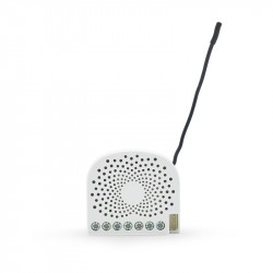
Bypass para...
-
Qubino...
-
Qubino...
-
Philio...
-
AEOTEC -...
-
AEOTEC -...
-
AEOTEC -...
-
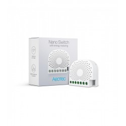
Aeotec Nano...
-
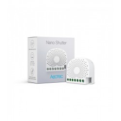
Aeotec Nano...
-
Qubino Mini...
-
Dimmer...
-
Chave de...
-
WiDom Smart...
-
Qubino...
-
Fibaro...
-
Micromódulo...
-
Controlador...
-
FIBARO...
-
HELTUN -...
-
Heatit ZM...
-
Philio...
-
ZOOZ...
-
Philio...
-
Philio...
-
Controlador...
-
Heatit ZM...
-
Termostato...
-
Shelly...
-
Shelly...
-
Shelly...