
Ningún producto
Precios con IVA incluído
Producto añadido correctamente a su carrito de la compra
Hay 0 artículos en su carrito. Hay 1 artículo en su cesta.


HELTUN - 'Quinto' módulo interruptor 5 canales Z-Wave+ 700
HE-RS01
Nuevo
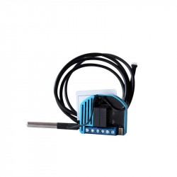
El módulo de conmutación HELTUN Quinto es un relé múltiple con cinco salidas de contacto seco. Puede controlar cualquier tipo de carga hasta 5A por salida.
Sin Stock
- Eliminar de mis favoritos
- Agregar este producto a mis favoritos
- Imprimir

Características técnicas
| Tecnología | Z-Wave Plus |
Descripción
TU COMODIDAD IMPORTA.
Cuando consideras tu comodidad en casa, ¿qué es lo más importante? ¿Puedes encender o apagar las luces sin pasar por diferentes habitaciones? ¿O ser capaz de cerrar la puerta, cerrar las persianas y atenuar las luces con un solo toque? ¿O tal vez algo más? Lo que necesites, HELTUN te tiene cubierto.
Toma el control
Cinco relés con contactos secos que soportan una carga de 5 amperios cada uno. La avanzada tecnología de cruce de cero de HELTUN ofrece un aumento significativo de la longevidad y la fiabilidad. Controla la iluminación o cualquier dispositivo: puerta, compuerta, persiana, válvula motorizada, ...
Increíblemente pequeño e inteligente
El módulo del quinto interruptor con control del obturador, ofrece increíbles capacidades a cualquier dispositivo conectado. Hace que los interruptores de luz sean "inteligentes" con un avanzado monitoreo remoto, control y programabilidad. Esto aporta la comodidad del control y la automatización de las aplicaciones de los teléfonos inteligentes a dispositivos "tontos" como interruptores de luz, cerraduras electrónicas de puertas, portones eléctricos, persianas, ventanas y válvulas.
Por ejemplo, puedes controlar hasta...
Cinco dispositivos de encendido y apagado
Tres dispositivos de encendido y apagado y un motor bidireccional
Un dispositivo de encendido y apagado y dos motores bidireccionales
A 26 mm de profundidad, el módulo de conmutación del quinto es también "increíblemente pequeño", encajando en cualquier caja de conexiones eléctricas rectangulares, redondas o cuadradas, incluso detrás de los dispositivos conectados.
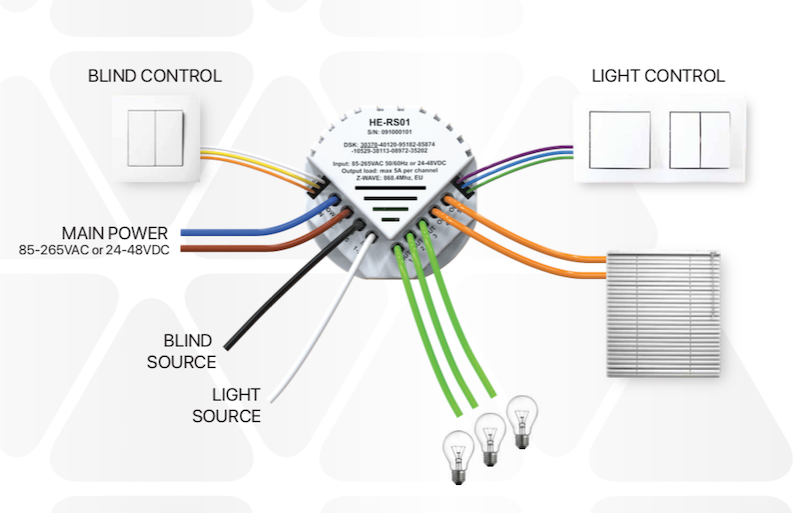
Entradas y salidas
La entrada de energía principal puede ser de 85-265VAC o 12-48VDC. El módulo del quinto interruptor tiene cinco salidas de relé con una carga máxima de 5 amperios cada una.
También tiene dos entradas independientes para los canales de relé que permiten controlar sistemas con diferentes fuentes de energía o utilizar las salidas como contactos secos: por ejemplo, para encender o apagar luces de 220VAC y para controlar válvulas motorizadas con alimentación de 24VDC.
También tiene seis entradas de cable piloto: una común y cinco para cada canal de transmisión. Esto permite que el módulo del quinto interruptor sea controlado por hasta cinco fuentes diferentes (por ejemplo, cinco interruptores de luz diferentes) y controlar todas las salidas de relé por separado.
Cada canal de transmisión utiliza la avanzada tecnología de HELTUN para proporcionar un aumento significativo de la longevidad y la fiabilidad.
Conozca su consumo de energía
El sistema integrado de consumo de energía monitoriza con precisión la cantidad de energía que ha utilizado en el transcurso de un día, una semana o un mes. ¿Sus actuales interruptores de luz hacen esto?
Simplemente especifique el consumo de carga en vatios para cada canal de relé y la lógica en el módulo del quinto interruptor calculará el consumo total basado en el tiempo desde que la salida estuvo en el estado "ON".
Heltun también ha diseñado el circuito para que consuma casi cero vatios de potencia cuando está en modo de espera. Esto ahorra energía y dinero, especialmente si su casa está equipada con muchos productos HELTUN.
Haz que tus interruptores sean increíblemente inteligentes
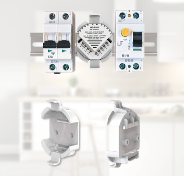
¿Tu carril DIN es un carril "estúpido"?
Como el módulo de conmutación de HELTUN tiene 5 canales cada uno capaz de manejar hasta 5 amperios, es un complemento perfecto para su panel de interruptores para monitorear y controlar grupos de dispositivos desde Internet a través de una puerta de enlace de Onda Z, como por ejemplo:
Grupos enteros de luces
Válvulas motorizadas
Las cerraduras de las puertas
Toldos, puertas y portones motorizados
El adaptador de montaje del módulo está disponible como accesorio para adaptarse a los carriles DIN estándar (50 mm), o también se puede montar directamente en la pared con los tornillos y tacos suministrados.
Poderosamente personalizable
Hay siete modos diferentes seleccionables para el módulo del quinto interruptor con hasta cinco cables piloto utilizados para controlar cualquier salida de relé de dispositivos como un interruptor de pared, un panel de alarma, etc.
Estado inverso - Si está encendido, se apaga cuando el circuito del cable piloto se cierra (o si está apagado, se enciende).
Momentánea - Se enciende cuando el circuito del cable piloto está cerrado, se apaga cuando el circuito del cable piloto está abierto.
Momentánea inversa - Se apaga cuando el circuito del cable piloto está abierto, se enciende cuando está cerrado.
Sólo encendido - Cuando el circuito del cable piloto está cerrado (es decir, en cortocircuito).
Sólo apagado - Cuando el circuito del cable piloto está cerrado (es decir, en cortocircuito).
La salida del módulo del quinto interruptor también puede ser controlada por un temporizador interno. Por ejemplo, después de encender el interruptor, se puede configurar para que se apague automáticamente más tarde (o viceversa: se enciende después de ser apagado).
Esta función puede utilizarse para abrir o cerrar puertas de garaje, portones, persianas, cortinas, cerraduras, etc., y luego devolverlas a su estado anterior sin necesidad de más entradas.
Temporizador (ON y OFF) - Se enciende cuando el circuito del cable piloto se cierra, y luego se apaga después de un tiempo especificado.
Temporizador (APAGADO y ENCENDIDO) - Se apaga cuando el circuito del cable piloto se cierra, y se enciende después de un tiempo especificado.
Control de los dispositivos motorizados
El módulo de conmutación de HELTUN hace más que controlar la iluminación de su casa. Puedes usarlo para controlar persianas motorizadas, cortinas, puertas de garaje, puertas de entrada y cerraduras eléctricas. Tienes control total sobre la programación de los diferentes botones para funciones específicas.
Por ejemplo, puede designar el botón superior izquierdo para subir las persianas de la sala de estar y el botón inferior izquierdo para bajarlas. En este modo, si se levantan las persianas y luego se presiona el botón de abajo, el sistema cancela automáticamente el comando ARRIBA e inicia un comando ABAJO, o viceversa.
El sistema también calcula la posición de las persianas cuando están completamente abiertas o cerradas y detiene automáticamente el motor cuando llega al límite de arriba o abajo.
Programación y escenarios
Usando el temporizador interno del módulo de interruptor de quinto HELTUN, puedes crear una programación para ciertos dispositivos. Por ejemplo:
Abrir las persianas a las 7:00 a.m. y cerrarlas a las 10:00 p.m.
Enciende la luz del porche a las 7:00 p.m. y apágala a la 1:00 a.m.
Las posibilidades de añadir comodidad y confort son infinitas y sólo están limitadas por la creatividad del propietario o instalador del módulo de conmutación HELTUN quinto.
Fácil de instalar
El módulo del quinto interruptor puede instalarse fácilmente en cualquier caja de conexiones eléctricas estándar (cuadrada o redonda). La instalación sólo debe ser realizada por una persona capacitada en el manejo de sistemas eléctricos de alta tensión.
Z-Wave Plus V2 certificado
Puedes conectar los dispositivos HELTUN a un controlador de automatización del hogar utilizando la última plataforma Z-Wave Plus V2 700. HELTUN cuenta con la avanzada tecnología Smart Start para una fácil integración del sistema y el marco de seguridad S2 con encriptación AES 256 para una transferencia de datos segura.
El módulo de conmutación de HELTUN es compatible con todos los controladores y dispositivos certificados Z-Wave que implementan correctamente las clases de control del interruptor táctil de Z-Wave. Con un controlador Z-Wave, puede gestionar todas las funciones del interruptor a través de una aplicación móvil, incluyendo cambios de temperatura, mostrar gráficos de consumo de energía y más.
Se pueden conectar hasta 50 dispositivos separados al módulo de conmutación de HELTUN. Puedes combinarlo con cualquier interruptor de encendido y apagado compatible con la Z-Wave u otro interruptor táctil para controlar diferentes sistemas en una habitación.
Los dispositivos HELTUN son compatibles con todas las frecuencias de Z-Wave para diferentes países (Europa, Rusia, Israel, Australia, EE.UU., India, Hong Kong, China, Japón y Corea). La frecuencia correcta se puede seleccionar en el menú del dispositivo.
HELTUN lanza periódicamente un nuevo firmware para el dispositivo con características adicionales que pueden ser actualizadas remotamente a través de un proceso OTA (Over-The-Air) cifrado.
FUNCIONES:
Opciones de inclusión/exclusión de la red Z-Wave
No está garantizado
S0 Seguro...
S2 no permitido, S2 permitido con llave
Control de asociación con 50 dispositivos de red
Control de dispositivos motorizados (modo persiana)
Cada una de las 5 entradas de cable piloto puede controlar cualquiera de las 5 salidas de relé.
Hasta 5 salidas pueden ser controladas por un cable piloto
Siete modos para cada salida:
Enciende sólo
Desactivar sólo
Invertir el estado (ON a OFF o OFF a ON)
Momentánea (ON cuando está en cortocircuito, OFF cuando se libera)
Momentánea invertida (OFF cuando está en cortocircuito, ON cuando se libera)
Temporizador (ON y OFF después del tiempo especificado)
Temporizador (OFF y ON después del tiempo especificado)
Cada salida de relé puede ser administrada por una puerta de enlace de Z-Wave o un dispositivo asociado.
Cada cable piloto puede desencadenar escenas
Modo de programación
Lógica del software de consumo de energía
Botón de restablecimiento de fábrica
La tecnología SmartStart para una rápida adición a las redes de Z-Wave
Actualización del firmware de OTA (Over-The-Air) encriptado
DATOS TÉCNICOS:
Dimensiones: 50x50x26 mm
Material: Plástico retardante del fuego
Color: Blanco
Cinco relés para cargas resistivas de hasta 5A cada uno
Dos entradas de relé independientes (contacto seco)
Conmutación de relés con HELTUN Tecnología Avanzada de Paso Cero
Vida de los relés: 100.000 ciclos
Un cable común (S) y cinco cables piloto (S1, S2, S3, S4, S5) para el control externo
Lógica del software de consumo de energía
Fuente de alimentación: 85-265VAC 50Hz / 60Hz, o 24-48VDC
Consumo de energía: <1 W
Temperatura de funcionamiento: 0 ° С a + 60 ° С
Clase de IP: IP21
SDK Z-Wave Plus V2: V7.11
Módulo de Z-Wave: ZGM130S
Ensamblado:
Caja de conexiones eléctricas: redonda o cuadrada, profundidad mínima 40 mm.
Adaptador opcional para rieles DIN (50 mm de ancho) o montaje en pared
Información Ampliada Z-Wave (Inglés)
Descargue el manual desde aquí.
1. Ensure the HE-RS01 is Powered On and the LED indicator blinks red slowly (i.e. it is excluded)
2. Start the inclusion mode from the gateway / controller
3. To start the inclusion process on the HE-RS01, double-press the service button on the device (with no more than a one-second interval between presses).
4. The LED indicator will blink green quickly.
5. If the inclusion has been successful, the LED indicator will turn green for three seconds then continue slowly blinking green continuously while the HE-RS01 is Powered On.
6. If the inclusion was not successful, the LED indicator will turn red for three seconds then continue slowly blinking red continuously while Powered On. In that case repeat the inclusion process (2-5) above.
1. Ensure the HE-RS01 is Powered On and the LED indicator is slowly blinking green (i.e. it is included in a Z-Wave network).
2. Start the exclusion mode from the gateway/controller.
3. To start the exclusion process on the HE-RS01, double-press the service button on the device (with no more than a one-second interval between presses).
4. The LED indicator will blink red quickly.
5. If the inclusion has been successful, the LED indicator will turn red for three seconds then continue blinking red slowly continuously while the HE-RS01 is Powered On.
6. If the inclusion was not successful, the LED indicator will turn green for three seconds then continue slow blink green all the time the device is Powered On. In that case repeat the exclusion process (2-5) above.
Note: If the HE-RS01 has previously been part of a Z-Wave network and has not been excluded since (the LED indicator will blink green slowly). Inclusion is not possible without first performing an Exclusion or Factory Reset procedure.
NOTE: This factory reset procedure will change all parameters to the original factory default values and will also exclude the device from any associated Z-Wave network.
Opiniones
30 otros productos de la misma categoría:
-
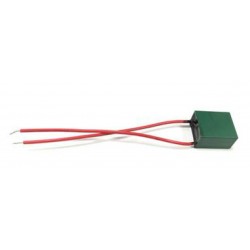
Bypass para...
-
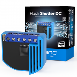
Qubino...
-
Qubino...
-
Philio...
-
AEOTEC -...
-
AEOTEC -...
-
AEOTEC -...
-
Aeotec Nano...
-
Aeotec Nano...
-
Qubino Mini...
-
WiDom Smart...
-
WiDom Smart...
-
WiDom Smart...
-
Qubino...
-
Fibaro...
-
Fibaro...
-
FIBARO RGBW...
-
FIBARO...
-
HELTUN -...
-
Heatit ZM...
-
Philio...
-
ZOOZ...
-
Philio...
-
Philio...
-
Controlador...
-
Heatit ZM...
-
Heatit ZM...
-
Shelly...
-
Shelly...
-
Shelly...