
Sem produtos
Preços com IVA
Produto adicionado com sucesso ao seu carrinho de compras
Existem 0 produtos no seu carrinho de compras. Existe um produto no seu carrinho de compras.


HELTUN - Quinto módulo de chave de 5 canais Z-Wave + 700
HE-RS01
Novo
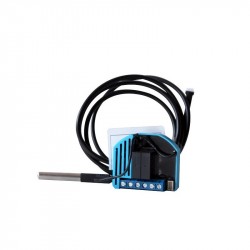
O módulo de chave HELTUN Quinto é um relé múltiplo com cinco saídas de contato seco. Pode controlar qualquer tipo de carga até 5A por saída.
Não disponível
- Retirar este produto da minha lista de favoritos.
- Adicionar este produto à minha lista de favoritos.

Características tecnicas
| Tecnologia | Z-Wave Plus |
Mais Informação
SEU CONFORTO É IMPORTANTE.
Quando você considera o seu conforto em casa, o que é mais importante? Você pode ligar ou desligar as luzes sem passar por salas diferentes? Ou ser capaz de fechar a porta, fechar as cortinas e diminuir as luzes com um toque? Ou talvez outra coisa? Tudo o que você precisa, HELTUN tem tudo o que você precisa.
Assumir o controle
Cinco relés de contato seco que carregam uma carga de 5 amperes cada. A avançada tecnologia zero-crossing da HELTUN oferece um aumento significativo na longevidade e na confiabilidade. Controle a iluminação ou qualquer dispositivo: porta, portão, veneziana, válvula motorizada, ...
Incrivelmente pequeno e inteligente
O quinto módulo de chave com controle de obturador oferece recursos incríveis para qualquer dispositivo conectado. Torna os interruptores de luz "inteligentes" com monitoramento, controle e programação remotos avançados. Isso traz a conveniência de controlar e automatizar aplicativos de smartphones para dispositivos "burros", como interruptores de luz, fechaduras eletrônicas, portões elétricos, persianas, janelas e válvulas.
Por exemplo, você pode controlar até ...
Cinco dispositivos ligados e desligados
Três dispositivos on / off e um motor bidirecional
Um dispositivo liga / desliga e dois motores bidirecionais
Com 26 mm de profundidade, o módulo de chave do 5º também é "incrivelmente pequeno", cabendo em qualquer caixa de junção elétrica retangular, redonda ou quadrada, mesmo atrás de dispositivos conectados.
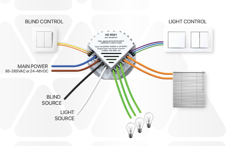
Entradas e saídas
A entrada de alimentação principal pode ser 85-265 VCA ou 12-48 VCC. O quinto módulo de chave possui cinco saídas de relé com uma carga máxima de 5 amperes cada.
Possui ainda duas entradas independentes para os canais de relé que permitem controlar sistemas com diferentes fontes de energia ou utilizar as saídas como contatos secos: por exemplo, para ligar ou desligar lâmpadas 220VAC e controlar válvulas motorizadas com potência 24VDC.
Também possui seis entradas de fio piloto: uma comum e cinco para cada canal de transmissão. Isso permite que o quinto módulo de chave seja controlado por até cinco fontes diferentes (por exemplo, cinco chaves de luz diferentes) e controle todas as saídas de relé separadamente.
Cada canal de transmissão usa tecnologia HELTUN avançada para fornecer um aumento significativo na longevidade e confiabilidade.
Conheça o seu consumo de energia
O sistema integrado de consumo de energia monitora com precisão a quantidade de energia que você usou ao longo de um dia, uma semana ou um mês. Seus interruptores de luz atuais fazem isso?
Basta especificar o consumo de carga em watts para cada canal de relé e a lógica no quinto módulo de chave calculará o consumo total com base no tempo desde que a saída esteve no estado "ON".
Heltun também projetou o circuito para consumir quase zero watts de energia quando em modo de espera. Isso economiza energia e dinheiro, especialmente se sua casa estiver equipada com muitos produtos HELTUN.
Torne seus interruptores incrivelmente inteligentes
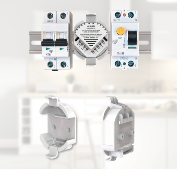
O seu trilho DIN é um trilho "estúpido"?
Como o módulo de switch HELTUN tem 5 canais, cada um capaz de lidar com até 5 amperes, é um complemento perfeito para seu painel de switch para monitorar e controlar grupos de dispositivos da Internet através de um gateway Z-Wave, como por exemplo:
Grupos inteiros de luzes
Válvulas motorizadas
Fechaduras
Toldos, portões e portões motorizados
O adaptador de montagem do módulo está disponível como um acessório para se encaixar em trilhos DIN padrão (50 mm) ou também pode ser montado diretamente na parede usando os parafusos e plugues fornecidos.
Poderosamente personalizável
Existem sete modos selecionáveis diferentes para o quinto módulo de chave com até cinco fios piloto usados para controlar qualquer saída de relé de dispositivos, como um interruptor de parede, um painel de alarme, etc.
Estado reverso - Se ligado, desliga quando o circuito do fio piloto fecha (ou se desligado, liga).
Momentâneo - Acende quando o circuito do fio piloto é fechado, apaga quando o circuito do fio piloto está aberto.
Momentary Reverse - Desliga quando o circuito do fio piloto está aberto, liga quando fechado.
Somente ligado - Quando o circuito do fio piloto está fechado (ou seja, em curto).
Somente desligado - quando o circuito do fio piloto está fechado (ou seja, em curto).
A saída do quinto módulo de chave também pode ser controlada por um temporizador interno. Por exemplo, após a chave ser ligada, ela pode ser configurada para desligar automaticamente mais tarde (ou vice-versa: ela liga depois de ser desligada).
Esta função pode ser usada para abrir ou fechar portas de garagem, portões, persianas, cortinas, fechaduras, etc., e depois devolvê-los ao estado anterior sem a necessidade de outras entradas.
Temporizador (LIGADO e DESLIGADO) - Acende quando o circuito do fio piloto fecha e desliga após um tempo especificado.
Temporizador (DESLIGADO e LIGADO) - Desliga quando o circuito do fio piloto fecha e liga após um tempo especificado.
Controle de dispositivos motorizados
O módulo de chave HELTUN faz mais do que controlar a iluminação da sua casa. Você pode usá-lo para controlar persianas motorizadas, cortinas, portas de garagem, portas de entrada e fechaduras elétricas. Você tem controle total sobre a programação dos diferentes botões para funções específicas.
Por exemplo, você pode designar o botão superior esquerdo para aumentar as cortinas da sala e o botão inferior esquerdo para baixá-las. Neste modo, se as cortinas forem levantadas e o botão para baixo for pressionado, o sistema cancela automaticamente o comando PARA CIMA e inicia um comando PARA BAIXO, ou vice-versa.
O sistema também calcula a posição das cortinas quando estão totalmente abertas ou fechadas e para automaticamente o motor quando atinge o limite superior ou inferior.
Programação e cenários
Usando o temporizador interno do 5º módulo de chave HELTUN, você pode criar uma programação para determinados dispositivos. Por exemplo:
Abra as cortinas às 7h e feche-as às 22h
Acenda a luz da varanda às 19h e apague-a à 1h
As possibilidades de adicionar comodidade e conforto são infinitas e limitadas apenas pela criatividade do proprietário ou instalador do 5º módulo de chave HELTUN.
Fácil de instalar
O quinto módulo de chave pode ser facilmente instalado em qualquer caixa de junção elétrica padrão (quadrada ou redonda). A instalação deve ser realizada apenas por uma pessoa treinada no manuseio de sistemas elétricos de alta tensão.
Certificado Z-Wave Plus V2
Você pode conectar dispositivos HELTUN a um controlador de automação residencial usando a plataforma Z-Wave Plus V2 700. HELTUN apresenta tecnologia Smart Start avançada para fácil integração do sistema e estrutura de segurança S2 com criptografia AES 256 para transferência perfeita. dados seguros.
O módulo de chave HELTUN é compatível com todos os controladores e dispositivos certificados Z-Wave que implementam corretamente as classes de controle de chave de toque Z-Wave. Com um controlador Z-Wave, você pode gerenciar todas as funções do switch por meio de um aplicativo móvel, incluindo mudanças de temperatura, exibição de gráficos de consumo de energia e muito mais.
Até 50 dispositivos separados podem ser conectados ao módulo de chave HELTUN. Você pode combiná-lo com qualquer botão liga / desliga compatível com Z-Wave ou outro botão tátil para controlar diferentes sistemas em uma sala.
Os dispositivos HELTUN são compatíveis com todas as frequências Z-Wave para diferentes países (Europa, Rússia, Israel, Austrália, EUA, Índia, Hong Kong, China, Japão e Coréia). A frequência correta pode ser selecionada no menu do dispositivo.
A HELTUN lança periodicamente novo firmware para o dispositivo com recursos adicionais que podem ser atualizados remotamente por meio de um processo OTA (Over-The-Air) criptografado.
FUNÇÕES:
Opções de inclusão / exclusão de rede Z-Wave
Não é garantido
S0 Seguro ...
S2 não permitido, S2 permitido com chave
Controle de associação com 50 dispositivos de rede
Controle de dispositivos motorizados (modo cego)
Cada uma das 5 entradas do fio piloto pode controlar qualquer uma das 5 saídas de relé.
Até 5 saídas podem ser controladas por um fio piloto
Sete modos para cada saída:
Ligue apenas
Desativar apenas
Inverter estado (ON para OFF ou OFF para ON)
Momentâneo (LIGADO quando em curto, DESLIGADO quando liberado)
Momentâneo invertido (DESLIGADO quando em curto, LIGADO quando liberado)
Temporizador (ON e OFF após o tempo especificado)
Temporizador (DESLIGADO e LIGADO após o tempo especificado)
Cada saída de relé pode ser gerenciada por um gateway Z-Wave ou um dispositivo parceiro.
Cada fio piloto pode desencadear cenas
Modo de programação
Lógica do software de consumo de energia
Botão de redefinição de fábrica
Tecnologia SmartStart para adição rápida a redes Z-Wave
Atualização de firmware criptografado OTA (Over-The-Air)
DADOS TÉCNICOS:
Dimensões: 50x50x26 mm
Material: plástico retardador de fogo
Cor branca
Cinco relés para cargas resistivas de até 5A cada
Duas entradas de relé independentes (contato seco)
Comutação de relé com tecnologia HELTUN Advanced Zero Pass
Vida do relé: 100.000 ciclos
Um fio comum (S) e cinco fios piloto (S1, S2, S3, S4, S5) para controle externo
Lógica do software de consumo de energia
Fonte de alimentação: 85-265VAC 50Hz / 60Hz ou 24-48VDC
Consumo de energia: <1W
Temperatura de operação: 0 °! em + 60 °!
Classe IP: IP21
Z-Wave Plus V2 SDK: V7.11
Módulo Z-Wave: ZGM130S
Montagem:
Caixa de ligações elétricas: redonda ou quadrada, profundidade mínima 40 mm.
Adaptador opcional para trilhos DIN (50 mm de largura) ou montagem em parede
Informação alargada da Z-Wave (Inglês)
Descarregue o manual a partir de aqui.
1. Ensure the HE-RS01 is Powered On and the LED indicator blinks red slowly (i.e. it is excluded)
2. Start the inclusion mode from the gateway / controller
3. To start the inclusion process on the HE-RS01, double-press the service button on the device (with no more than a one-second interval between presses).
4. The LED indicator will blink green quickly.
5. If the inclusion has been successful, the LED indicator will turn green for three seconds then continue slowly blinking green continuously while the HE-RS01 is Powered On.
6. If the inclusion was not successful, the LED indicator will turn red for three seconds then continue slowly blinking red continuously while Powered On. In that case repeat the inclusion process (2-5) above.
1. Ensure the HE-RS01 is Powered On and the LED indicator is slowly blinking green (i.e. it is included in a Z-Wave network).
2. Start the exclusion mode from the gateway/controller.
3. To start the exclusion process on the HE-RS01, double-press the service button on the device (with no more than a one-second interval between presses).
4. The LED indicator will blink red quickly.
5. If the inclusion has been successful, the LED indicator will turn red for three seconds then continue blinking red slowly continuously while the HE-RS01 is Powered On.
6. If the inclusion was not successful, the LED indicator will turn green for three seconds then continue slow blink green all the time the device is Powered On. In that case repeat the exclusion process (2-5) above.
Note: If the HE-RS01 has previously been part of a Z-Wave network and has not been excluded since (the LED indicator will blink green slowly). Inclusion is not possible without first performing an Exclusion or Factory Reset procedure.
NOTE: This factory reset procedure will change all parameters to the original factory default values and will also exclude the device from any associated Z-Wave network.
Avaliações
30 outros produtos na mesma categoria:
-
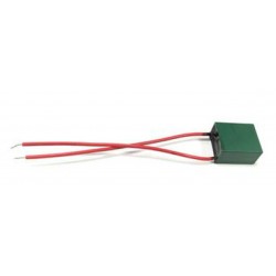
Bypass para...
-
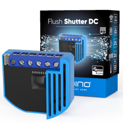
Qubino...
-
Qubino...
-
Philio...
-
AEOTEC -...
-
AEOTEC -...
-
AEOTEC -...
-
Aeotec Nano...
-
Aeotec Nano...
-
Qubino Mini...
-
Dimmer...
-
Chave de...
-
WiDom Smart...
-
Qubino...
-
Fibaro...
-
Micromódulo...
-
Controlador...
-
FIBARO...
-
HELTUN -...
-
Heatit ZM...
-
Philio...
-
Philio...
-
Philio...
-
Controlador...
-
Heatit ZM...
-
Termostato...
-

Shelly...
-
Shelly...
-

Shelly...
-
Shelly...