Productos más vistos


Confianza Online


domoticalia.es/es/ Reviews with ekomi.es
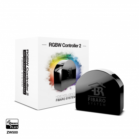
EN OFERTA FIBARO RGBW Controller 2 Ver más grande

FIBARO RGBW Controller 2

FGRGBW-442

Nuevo

Este controlador RGB/RGBW puede controlar tiras de LED, LEDs RGB/RGBW y fuentes de luz de 12V o 24V. Además permite hacer muchas otras cosas en domotica Z-Wave

Más detalles

En Stock - Envío inmediato

63,89 €

-20%

79,86 €

Características técnicas

Tecnología Z-Wave Plus
Característica Dimmer

Descripción

FIBARO RGBW Controller 2 es un controlador universal compatible con Z-Wave Plus.
Controlador RGB/RGBW.
El FIBARO RGBW Controller 2 utiliza la señal de salida PWM, lo que le permite
tiras de LED, RGB, RGBW, luces halógenas y otras luces resistivas.
cargas. También puede medir la potencia activa y la energía consumida por el
carga. Los dispositivos controlados pueden ser alimentados por 12 o 24V DC.
Las entradas soportan interruptores momentáneos/toggle y sensores analógicos de 0-10V, como sensores de temperatura, sensores de humedad, sensores de luz, etc.

Desata tu fantasía y expresa tu estado de ánimo con luz de colores! Con el Fibaro RGBW Controller 2 usted pinta su cuarto de baño con luz usando rayas LED, ajustadas a la temperatura del agua de su bañera. O haga que la luz de su casa se ponga roja tan pronto como se active un sensor de alarma. Hay 3 millones de colores a su disposición. Así que el único límite es tu imaginación.

Gracias al módulo de radio compacto, puede integrar las luces LED RGB y RGBW conectadas en su red Z-Wave. Con el mando a distancia, el smartphone o la automatización controlada por sensores puede conmutar y atenuar los LED y seleccionar cualquier valor de color.

Características:

Módulo de radio para la instalación de cajas de pared
Conmutador, atenuador y función de selección de color RGBW
Función de medición de energía
Tensión: 12 V o 24 V DC
Max. Salida: 6 Un solo canal, 12 A todos los canales de salida en total
Consumo de energía: < 0.3 W
Hasta 4 sensores analógicos (0-10 V) conectables (sensores no incluidos en la entrega)
Tecnología inalámbrica: Z-Wave Plus
Seguridad: S2
SmartStart habilitado
Dimensión: 42 x 38 x 18 mm

Información Ampliada Z-Wave (Inglés)

Nombre: RGBW Controller 2
Fabricante:FIBARO
Identificador:FGRGBW-442
Número de Certificación Z-Wave:ZC10-19086715
Plataforma Hardware:ZM5101
FLiRS:NO
Tipo de Role:Always On Slave
Descripción Corta:FIBARO RGBW Controller 2 is a universal, Z-Wave Plus compatible RGB/RGBW controller.
Descripción:FIBARO RGBW Controller 2 is a universal, Z-Wave Plus compatible RGB/RGBW controller. FIBARO RGBW Controller 2 uses PWM output signal, allowing it to control LED, RGB, RGBW strips, halogen lights and other resistive loads. It can also measure active power and energy consumed by the load. Controlled devices may be powered by 12 or 24V DC. Inputs support momentary/toggle switches and 0-10V analog sensors, like temperature sensors, humidity sensors, light sensors etc. Main features of FIBARO RGBW Controller: • Compatible with any certified Z-Wave or Z-Wave Plus controller. • Supports Z-Wave network Security Modes: S0 with AES-128 encryption and S2 Authenticated with PRNG-based encryption. • Works as a Z-Wave signal repeater. • Allows for controlling: » RGB/RGBW LED strip, » one-color LED strips, » halogen lights, » other compliant resistive loads. • Allows for connecting to inputs: » switches/buttons, » 0-10V analog sensors or potentiometers. • Active power and energy metering.

Descargue el manual desde aquí.

Grupo
Max Nodos
Descripción
1
1
“Lifeline” reports the device status and allows for assigning single device only (main controller by default).
2
5
“RGBW Sync” allows to synchronize state of other FIBARO RGBW Controller 2 devices (do not use with other devices).
3
5
“On/Off (IN1)” is used to turn the associated devices on/off reflecting IN1 operation.
4
5
“Dimmer (IN1)” is used to change level of associated devices reflecting IN1 operation.
5
5
“On/Off (IN2)” is used to turn the associated devices on/off reflecting IN2 operation.
6
5
“Dimmer (IN2)” is used to change level of associated devices reflecting IN2 operation.
7
5
“On/Off (IN3)” is used to turn the associated devices on/off reflecting IN3 operation.
8
5
“Dimmer (IN3)” is used to change level of associated devices reflecting IN3 operation.
9
5
“On/Off (IN4)” is used to turn the associated devices on/off reflecting IN4 operation.
10
5
“Dimmer (IN4)” is used to change level of associated devices reflecting IN4 operation.
Número
Tamaño (Bytes)
Valor por Defecto
Nombre
Descripción
1
1
0
Remember device status before the power failure
This parameter determines how the device will react in the event of power supply failure (e.g. power outage or taking out from the electrical outlet). After the power supply is back on, the device can be restored to previous state or remain switched off.
150
1
0
Inputs - LED colour control mode
This parameter determines how connected switches control LED strips.
151
2
3
Local control - transition time
This parameter determines time of smooth transition between 0% and 100% when controlling with connected switches.
152
2
3
Remote control - transition time
This parameter determines time of smooth transition between initial and target state when controlling via Z-Wave network.
153
2
1023
Active reports
This parameter allows to select which reports are sent to Lifeline group. Values can be combined. Value 0 means none of the listed reports will be sent.
154
4
0
ON frame value for single click
This parameter defines value sent to devices in association groups. The parameters consist of 4 bytes, each byte reserved for separate channel, from least significant (IN1) to most significant (IN4).
155
4
0
OFF frame value for single click
This parameter defines value sent to devices in association groups. The parameters consist of 4 bytes, each byte reserved for separate channel, from least significant (IN1) to most significant (IN4).
156
4
0
ON frame value for double click
This parameter defines value sent to devices in association groups. The parameters consist of 4 bytes, each byte reserved for separate channel, from least significant (IN1) to most significant (IN4).
157
1
0
Start programmed sequence
Setting this parameter will start programmed sequence with selected number. User can define own sequences via controller.
20
1
2
Input 1 - operating mode
This parameter allows to choose mode of 1st input (IN1). Change it depending on connected device.
21
1
2
Input 2 - operating mode
This parameter allows to choose mode of 2nd input (IN2). Change it depending on connected device.
22
1
2
Input 3 - operating mode
This parameter allows to choose mode of 3rd input (IN3). Change it depending on connected device.
23
1
2
Input 4 - operating mode
This parameter allows to choose mode of 4th input (IN4). Change it depending on connected device.
30
4
0
Alarm configuration - 1st slot
This parameter determines to which alarm frames and how the device should react. The parameters consist of 4 bytes, three most significant bytes are set according to the official Z-Wave protocol specification. X – channels summarized: 1/2/3/4 channel are equal to values 1/2/4/8. Y – sequence number: 1-10 (parameter 157).
31
4
0
Alarm configuration - 2nd slot
This parameter determines to which alarm frames and how the device should react. The parameters consist of 4 bytes, three most significant bytes are set according to the official Z-Wave protocol specification. X – channels summarized: 1/2/3/4 channel are equal to values 1/2/4/8. Y – sequence number: 1-10 (parameter 157).
32
4
0
Alarm configuration - 3rd slot
his parameter determines to which alarm frames and how the device should react. The parameters consist of 4 bytes, three most significant bytes are set according to the official Z-Wave protocol specification. X – channels summarized: 1/2/3/4 channel are equal to values 1/2/4/8. Y – sequence number: 1-10 (parameter 157).
33
4
0
Alarm configuration - 4th slot
This parameter determines to which alarm frames and how the device should react. The parameters consist of 4 bytes, three most significant bytes are set according to the official Z-Wave protocol specification. X – channels summarized: 1/2/3/4 channel are equal to values 1/2/4/8. Y – sequence number: 1-10 (parameter 157).
34
4
0
Alarm configuration - 5th slot
This parameter determines to which alarm frames and how the device should react. The parameters consist of 4 bytes, three most significant bytes are set according to the official Z-Wave protocol specification. X – channels summarized: 1/2/3/4 channel are equal to values 1/2/4/8. Y – sequence number: 1-10 (parameter 157).
35
2
600
Duration of alarm signalization
This parameter determines duration of alarm signalization.
40
1
0
Input 1 - sent scenes
This parameter defines which actions result in sending scene ID and attribute assigned to them. Parameter is relevant only if parameter 20 is set to 2, 3 or 4.
41
1
0
Input 2 - sent scenes
This parameter defines which actions result in sending scene ID and attribute assigned to them. Parameter is relevant only if parameter 21 is set to 2, 3 or 4.
42
1
0
Input 3 - sent scenes
This parameter defines which actions result in sending scene ID and attribute assigned to them. Parameter is relevant only if parameter 22 is set to 2, 3 or 4.
43
1
0
Input 4 - sent scenes
This parameter defines which actions result in sending scene ID and attribute assigned to them. Parameter is relevant only if parameter 23 is set to 2, 3 or 4.
61
2
15
Power reports - on change
This parameter determines the minimum change in consumed power that will result in sending new power report to the main controller. For loads under 10W the parameter is not relevant and reports are sent every 2W change. Power reports are sent no oft en than every 30 seconds.
62
2
3600
Power reports - periodic
This parameter determines in what time intervals the periodic power reports are sent to the main controller. Periodic reports do not depend of power change (parameter 61).
63
2
5
Analog inputs reports - on change
This parameter defines minimal change (from the last reported) of analog input voltage that results in sending new report. Parameter is relevant only for analog inputs (parameter 20, 21, 22 or 23 set to 0 or 1). Analog inputs reports (Sensor Multilevel) are sent no often than every 30 seconds.
64
2
0
Analog inputs reports - periodic
This parameter defines reporting period of analog inputs value. Periodical reports are independent from changes in value (parameter 63). Parameter is relevant only for analog inputs (parameter 20, 21, 22 or 23 set to 0 or 1).
65
2
10
Energy reports - on change
This parameter determines the minimum change in consumed energy that will result in sending new energy report to the main controller. Energy reports are sent no often than every 30 seconds.
66
2
3600
Energy reports - periodic
This parameter determines in what time intervals the periodic energy reports are sent to the main controller. Periodic reports do not depend of energy change (parameter 65)
Switch Color V3
COMMAND_CLASS_SWITCH_COLOR_V3
Application Status
COMMAND_CLASS_APPLICATION_STATUS
Association Group Information V2
COMMAND_CLASS_ASSOCIATION_GRP_INFO_V2
Association V2
COMMAND_CLASS_ASSOCIATION_V2
Central Scene V3
COMMAND_CLASS_CENTRAL_SCENE_V3
Configuration
COMMAND_CLASS_CONFIGURATION
CRC16 Encapsulation
COMMAND_CLASS_CRC_16_ENCAP
Device Reset Locally
COMMAND_CLASS_DEVICE_RESET_LOCALLY
Firmware Update Meta-Data V4
COMMAND_CLASS_FIRMWARE_UPDATE_MD_V4
Manufacturer Specific V2
COMMAND_CLASS_MANUFACTURER_SPECIFIC_V2
Meter V3
COMMAND_CLASS_METER_V3
Multi-Channel Association V3
COMMAND_CLASS_MULTI_CHANNEL_ASSOCIATION_V3
Multi-Channel V4
COMMAND_CLASS_MULTI_CHANNEL_V4
Notification V8
COMMAND_CLASS_NOTIFICATION_V8
Powerlevel
COMMAND_CLASS_POWERLEVEL
Protection V2
COMMAND_CLASS_PROTECTION_V2
Security S0
COMMAND_CLASS_SECURITY
Security S2
COMMAND_CLASS_SECURITY_2
Sensor Multilevel V11
COMMAND_CLASS_SENSOR_MULTILEVEL_V11
Supervision
COMMAND_CLASS_SUPERVISION
Switch Color V3
COMMAND_CLASS_SWITCH_COLOR_V3
Transport Service V2
COMMAND_CLASS_TRANSPORT_SERVICE_V2
Version V2
COMMAND_CLASS_VERSION_V2
Z-Wave Plus Info V2
COMMAND_CLASS_ZWAVEPLUS_INFO_V2
Inclusion
To add the device to the Z-Wave network manually:

1. Power the device.

2. Set the main controller in (Security/non-Security Mode) add mode (see the controller’s manual).

3. Quickly, three times click the button.

4. If you are adding in Security S2 Authenticated, scan the DSK QR code or input the underlined part of the DSK (on the device label).

5. LED will start blinking yellow, wait for the adding process to end.

6. Successful adding will be confirmed by the Z-Wave controller’s message.


To add the device to the Z-Wave network using SmartStart:

1. Set the main controller in Security S2 Authenticated add mode (see the controller’s manual).

2. Scan the DSK QR code or input the underlined part of the DSK (on the device label).

3. Power the device.

4. LED will start blinking yellow, wait for the adding process to end.

5. Successful adding will be confirmed by the Z-Wave controller’s message


Exclusion
To remove the device from the Z-Wave network:

1. Power the device.

2. Set the main controller into remove mode (see the controller’s manual).

3. Quickly, three times click the button.

4. LED will start blinking yellow, wait for the removing process to end.

5. Successful removing will be confirmed by the Z-Wave controller’s message.

Factory Reset
Reset procedure allows to restore the device back to its factory settings, which means all information about the Z-Wave controller and user configuration will be deleted. Resetting to factory defaults does not reset energy consumption memory.

1. Press and hold the button to enter the menu.

2. Release the button when the device glows yellow.

3. Quickly click the button to confirm.

4. After a few seconds the device will be restarted, which is signaled with the red LED colour.


Use re- set procedure only if the primary controller is missing or inoperable.
Device Wake-Up
FIBARO RGBW 2 Controller is powered using DC power supply unit so it is always awake.
Electric Load Type
Select the electric load type(s) supported by the device.
Sensors
Sensor types supported by the product.
Supported Meter Type
Indicate which type of metering is supported by the device.
Color
If the product is only available in one color, pick the color from the list.
Supported Notification Types
Select the Notification Types that the product handles (controllers), or sends (slaves).


Opiniones

grado 
19/01/2021

Funciona estupendo

Conectado con el Fibaro HC3 y todo estupendo. Aún le falta la misma integración que tenía en el HC2, pero funciona muy bien.

¡Escriba su opinión!

Escribe tu opinión

FIBARO RGBW Controller 2

FIBARO RGBW Controller 2

Este controlador RGB/RGBW puede controlar tiras de LED, LEDs RGB/RGBW y fuentes de luz de 12V o 24V. Además permite hacer muchas otras cosas en domotica Z-Wave

5 otros productos de la misma categoría:

Los clientes que compraron este producto también han comprado...