Ningún producto
Precios con IVA incluído
Producto añadido correctamente a su carrito de la compra
Hay 0 artículos en su carrito. Hay 1 artículo en su cesta.


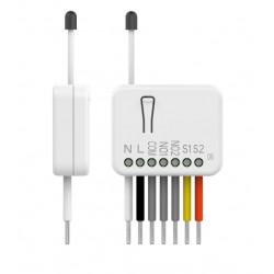
Fibaro -Double Switch 2- Micromodulo relé interruptor doble On / Off Z-Wave+ con medicion de consumo
FGS-223
Nuevo
El relé / interruptor en formato micromódulo Fibaro FGS-223 "Double Switch 2" le permitirá controlar dos luces o dos dispositivos remotos al tiempo que permite conservar el interruptor convencional existente.
En Stock - Envío inmediato
- Eliminar de mis favoritos
- Agregar este producto a mis favoritos
- Imprimir

Características técnicas
| Tecnología | Z-Wave Plus |
| Característica | Medición de Consumo |
Descripción
El nuevo micromódulo interruptor / relé doble de Fibaro, Fibaro FGS-223 "Double Switch 2" disponible como un interruptor doble Z-Wave, fue diseñado para activar y desactivar los dispositivos o cargas eléctricos. Gracias a su pequeño tamaño se puede montar en cajas de conexión o carcasas de dispositivos en el interior. El módulo se controla ya sea a través de la red Z-Wave o mediante un simple interruptor. Dispone de función de medida de potencia y consumo de energía de uso que le permite controlar y reducir sus facturas de electricidad. Conecte su Fibaro FGS-223 "Double Switch 2" en el sistema junto a otros dispositivos para disfrutar de las posibilidades casi infinitas!
Al tratarse de 1 relé doble dispone de 2 salidas:
- 6,5A (1.560W a 240V) máx. por salida con carga resistiva.
- 10A (2.400W a 240V) máx. por salida TOTAL con carga resistiva.
Dispone de un mecanismo de activación de escenas integrado
clases de comunicación y notificación de seguridad
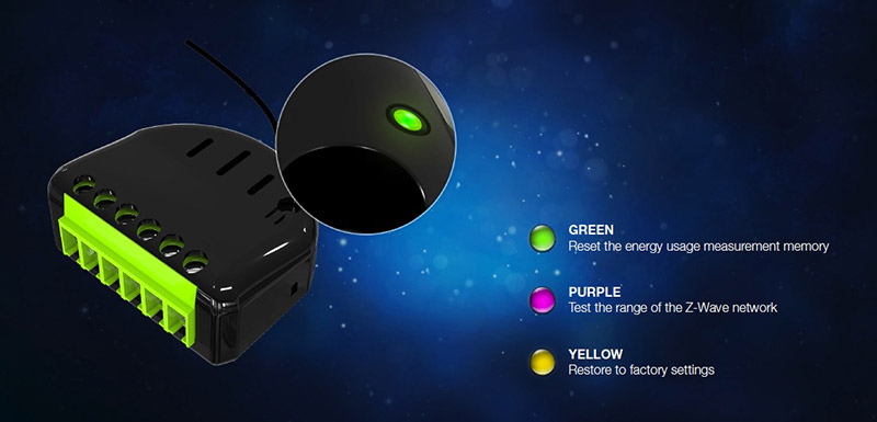
menú de configuración con un diodo
Última generación Z-Wave con chip de la serie 500
Compatible Z-Wave Plus
Realiza funciones de repetidor Z-Wave
Mide energía y potencia de los dispositivos conectados
Soporta el modo seguro (Red de Seguridad Z-Wave) con cifrado AES-128
Un complejo sistema de control para cada canal
Un complejo sistema de activación de escena para cada canal (manejo de la escena)
1 a 3 pulsaciones y manteniendo la tecla pulsada se pueden asignar a cuatro acciones diferentes
medición de energía muy precisa +/- 1% de potencia por encima de 5W
Notificaciones inteligentes
Conexiones mejoradas
menú de configuración sencillo
Dispone de testigo de prueba de cobertura de la red Z-Wave
Actualizaciones de software*
compatibilidad con la certificación confirmada por FCC, DEKRA, Z-Wave
Atención:
Tenga en cuenta que este módulo requiere de NEUTRO para operar. La salida no es libre de potencial, lo que no permite controlar un contacto seco o cargar otra tensión de alimentación de la entrada.
REPETIMOS: no puede ser utilizado en un esquema de conexión del tipo "contacto seco", como podía hacerlo su predecesor el Fibaro FGS-222.
Esquema de Cableado del relé Fibaro FGS-223
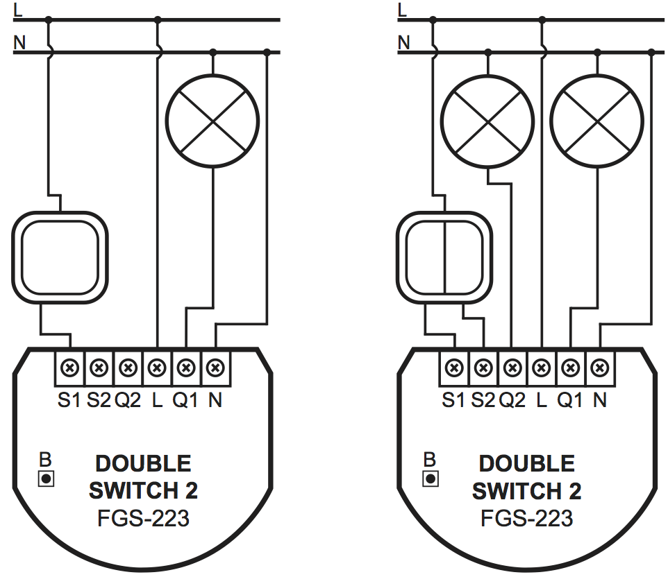
Imagen de cableado tanto con 1 como con 2 circuitos
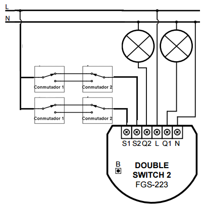
Esquema de Conexión para controlar 1 zona de iluminación con "llaves conmutadas":
Resumen:
2 salidas:
- 6,5A (1560W a 240V) máx. por salida con carga resistiva.
- 10A (2400W a 240V) máx. por salida TOTAL con carga resistiva.
la medición precisa de consumo (+/- 1% de 5W).
Z-Wave + 500 Series (mejor comunicación a distancia).
comunicaciones seguras con el cifrado AES-128.
Capacidad de desencadenar escenas de domótica * a través de las entradas S1 y S2 (4 posibles escenas por botón).
función de repetidor para extender la red Z-Wave.
Configuración con función de menú interactivo y probador de red Z-Wave con LED
 |
Información Ampliada Z-Wave (Inglés)
Descargue el manual desde aquí.
Active power and energy metering functionality
Z-Wave range tester
LED diode
2) Make sure the Switch 2 is within the direct range of your Z-Wave controller.
3) Connect the device in accordance with one of the diagrams included in the manual.
4) After verifying correctness of the connection switch on the mains voltage.
5) Identify the S1 switch or the B-button (located on the device’s housing).
6) Set the main controller in (security/non-security) add mode (see the controller’s manual).
7) Quickly, three times press the S1 switch or the B-button.
8) Wait for the adding process to end.
9) Successful adding will be confirmed by the Z-Wave controller’s message.
2) Identify the S1 switch or the B-button (located on the device’s housing).
3) Set the main controller in remove mode (see the controller’s manual).
4) Quickly, three times press the S1 switch or the B-button.
5) Wait for the removing process to end.
6) Successful removing will be confirmed by the Z-Wave controller’s message.
1) Switch off the mains voltage (disable the fuse).
2) Remove the Switch 2 from the wall switch box.
3) Switch on the mains voltage.
4) Press and hold the B-button to enter the menu.
5) Wait for the visual LED indicator to glow yellow.
6) Quickly release and click the B-button again.
7) After few seconds the device will be restarted, which is signalled with the red LED indicator colour.
Use reset procedure only if the primary controller is missing or inoperable.
Opiniones
Domtizar luces
Buen rele para domotizar luces encendido/apagado. Facil de parametrizar para pulsador con los parametros Z-Wave
Envio rapido
Asesoramiento correcto. Envio rapido y bien.
30 otros productos de la misma categoría:
-
Qubino...
-
Qubino...
-
Philio...
-
AEOTEC -...
-
AEOTEC -...
-
AEOTEC -...
-
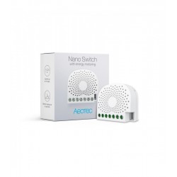
Aeotec Nano...
-
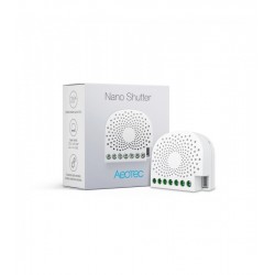
Aeotec Nano...
-
Qubino Mini...
-
WiDom Smart...
-
WiDom Smart...
-
WiDom Smart...
-

Qubino...
-
Fibaro...
-
Fibaro...
-
FIBARO RGBW...
-
FIBARO...
-
HELTUN -...
-
HELTUN -...
-
Heatit ZM...
-
Philio...
-
ZOOZ...
-
Philio...
-
Philio...
-
Controlador...
-
Heatit ZM...
-
Heatit ZM...
-
Shelly...
-
Shelly...
-
Shelly...