Sem produtos
Preços com IVA
Produto adicionado com sucesso ao seu carrinho de compras
Existem 0 produtos no seu carrinho de compras. Existe um produto no seu carrinho de compras.


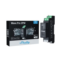
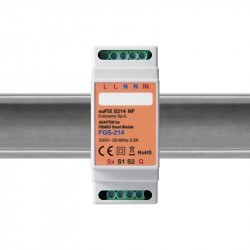
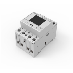
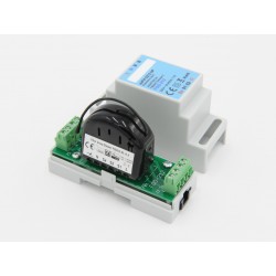
Shelly Qubino Wave PRO 1 - Módulo para calha DIN 1 relé de contacto seco Z-Wave 800
QPSW-0A1X16EU
Novo
Interruptor inteligente Z-Wave profissional de 1 canal em calha DIN com contactos secos, adequado para domótica e instalações com controlo remoto. Montagem em calha DIN no interior de uma caixa de disjuntores. Funções de segurança melhoradas.
Em estoque
- Retirar este produto da minha lista de favoritos.
- Adicionar este produto à minha lista de favoritos.

Características tecnicas
| Tecnologia | Z-Wave Serie 800 |
Mais Informação
O Wave Pro 1 é um interrutor inteligente monofásico de 1 canal, montável em calha DIN, que suporta até 16 A para a automatização de iluminação profissional e de aparelhos para utilização residencial ou comercial. Está equipado com uma saída sem potencial (contactos secos) que oferece uma grande flexibilidade em termos de tensão e de aplicações. Podem ser definidos diferentes tipos de acções, cenários e horários para sincronizar o seu ambiente com as suas actividades diárias ou necessidades comerciais.
Shelly Qubino funciona com Z-Wave
Através da Z-Wave, os produtos de domótica podem comunicar sem problemas entre si, independentemente da marca ou da plataforma, graças a um gateway inteligente centralizado! Os dispositivos Shelly Qubino funcionam com a última geração de chips Z-Wave (S800), uma das tecnologias normalizadas mais populares para casas inteligentes em todo o mundo.
Funciona com qualquer gateway Z-Wave
O Wave Pro 1 é compatível com versões anteriores e foi concebido para ser instalado atrás de interruptores/botões de pressão. Uma vez instalado, inclua o dispositivo na sua rede Z-Wave (é necessário um gateway Z-Wave) e controle-o através do seu smartphone ou tablet. Os dispositivos Shelly Qubino funcionam com mais de 4000 dispositivos e gateways certificados Z-Wave.
1 canal, 16 A
Tem uma saída total de 16 A.
Contactos secos
Suporta tensões baixas e altas, permitindo-lhe controlar uma vasta gama de dispositivos e aparelhos AC.
Montagem em calha DIN
Destina-se a ser instalado no interior do invólucro do disjuntor e foi concebido para cumprir a normalização global da calha DIN.
Associações
Estabeleça uma comunicação direta entre dispositivos na sua rede Z-Wave local e defina acções sem a necessidade de um gateway!
O mais alto nível de segurança
Inclua o dispositivo como Security 2 Authenticated para comunicação encriptada e máxima segurança da sua rede Z-Wave.
FUNÇÕES do Shelly Wave Pro 1
- 1 saída, 16 A
- Contactos livres de potencial (contactos secos)
- Montagem em calha DIN
- Consumo de energia extremamente baixo: < 0,3 W
- Banda de frequência Z-Wave: 868,4 MHz (países CEPT)
- Tecnologia mais recente: Z-Wave série 800
- Configuração automática com SmartStart
- Segurança 2 Autenticada para o mais alto nível de segurança
- Actualizações de firmware via rádio
- Funciona com gateways Z-Wave certificados e mais de 4000 dispositivos Z-Wave
ESPECIFICAÇÕES TÉCNICAS do Shelly Wave Pro 1
- Fonte de alimentação: 110-240 V AC, 50/60 Hz
- Consumo de energia: < 0,3 W
- Tensão máxima de comutação AC: 240 V
- Corrente máxima de comutação CA: 16 A
- Proteção contra sobreaquecimento: Sim
- Distância: Até 40 m em ambientes internos (dependendo das condições locais)
- Repetição Z-Wave: Sim
- Processador: Z-Wave S800
- Bandas de frequência Z-Wave: 868,4 MHz
- Potência máxima de radiofrequência emitida na(s) banda(s) de frequência: < 25 mW
- Dimensões (A x L x P): 94x19x69 ±0,5 mm
- Peso: 60 g
- Montagem: calha DIN
- Torque máximo do terminal de parafuso: 0,4 Nm
- Secção transversal do condutor: 0,5 a 2,5 mm / 20 a 14 AWG (conetor verde) 0,5 a 1,5 mm / 20 a 16 AWG (conectores brancos)
- Comprimento de descasque do condutor: 6 a 7 mm (conetor verde) 5 a 6 mm (conectores brancos)
- Material da caixa: Plástico
- Cor: Azul
- Temperatura ambiente : -20°C a 40°C
- Humidade: 30% a 70% HR
Informação alargada da Z-Wave (Inglês)
The first five digits of the key are highlighted or underlined to help the user identify the PIN Code part of the DSK text. The DSK is additionally represented with a QR Code as shown on the image.
Note! All Device outputs (O, O1, O2, etc. - depending on the Device type) will turn the load 1s on/1s off /1s on/1s off if the Device is successfully added to/removed from a Z-Wave® network.
Note! In case of Security 2 (S2) adding (inclusion), a dialog will appear asking you to enter the corresponding PIN Code (5 underlined digits) that are written on the Z-Wave® DSK label on the side of the Device and on the Z-Wave® DSK label inserted in the packaging.
IMPORTANT: The PIN Code must not be lost.
6.1.1 SmartStart adding (inclusion)
SmartStart enabled products can be added into a Z-Wave® network by scanning the Z-Wave® QR Code present on the Device with a gateway providing SmartStart inclusion. No further action is required, and the SmartStart device will be added automatically within 10 minutes of being switched on in the network vicinity.
1. With the gateway application scan the QR code on the Device label and add the Security 2 (S2) Device Specific Key (DSK) to the provisioning list in the gateway.
2. Connect the Device to a power supply.
3. Check if the blue LED is blinking in Mode 1. If so, the Device is not added to a Z-Wave® network.
4. Adding will be initiated automatically within a few seconds after connecting the Device to a power supply, and the Device will be added to a Z-Wave® network automatically.
5. The blue LED will be blinking in Mode 2 during the adding process.
6. The green LED will be blinking in Mode 1 if the Device is successfully added to a Z-Wave® network.
6.1.2 Adding (inclusion) with the S button
1. Connect the Device to a power supply.
2. Check if the blue LED is blinking in Mode 1. If so, the Device is not added to a Z-Wave® network.
3. Enable add/remove mode on the gateway.
4. To enter the Setting mode, quickly press and hold the S button on the Device until the LED turns solid blue.
5. Quickly release and then press and hold (> 2s) the S button on the Device until the blue LED starts blinking in Mode 3. Releasing the S button will start the Learn mode.
6. The blue LED will be blinking in Mode 2 during the adding process.
7. The green LED will be blinking in Mode 1 if the Device is successfully added to a Z-Wave® network.
Note! In Setting mode, the Device has a timeout of 10s before entering again into Normal mode.
6.1.3 Adding (inclusion) with a switch/push-button
1. Connect the Device to a power supply.
2. Check if the blue LED is blinking in Mode 1. If so, the Device is not added to a Z-Wave® network.
3. Enable add/remove mode on the gateway.
4. Toggle the switch/push-button connected to any of the SW terminals (SW, SW1, SW2, etc.) 3 times within 3 seconds (this procedure puts the Device in Learn mode*). The Device must receive on/off signal 3 times, which means pressing the momentary switch 3 times, or toggling the switch on and off 3 times.
5. The blue LED will be blinking in Mode 2 during the adding process.
6. The green LED will be blinking in Mode 1 if the Device is successfully added to a Z-Wave® network.
*Learn mode - a state that allows the Device to receive network information from the gateway.
Note! The Device will be removed from your Z-Wave® network, but any custom configuration parameters will not be erased.
Note! All Device outputs (O, O1, O2, etc. - depending on the Device type) will turn the load 1s on/1s off /1s on/1s off if the Device is successfully added to/removed from a Z-Wave® network.
6.2.1 Removing (exclusion) with the S button
1. Connect the Device to a power supply.
2. Check if the green LED is blinking in Mode 1. If so, the Device is added to a Z-Wave® network.
3. Enable add/remove mode on the gateway.
4. To enter the Setting mode, quickly press and hold the S button on the Device until the LED turns solid blue.
5. Quickly release and then press and hold (> 2s) the S button on the Device until the blue LED starts blinking in Mode 3. Releasing the S button will start the Learn mode.
6. The blue LED will be blinking in Mode 2 during the removing process.
7. The blue LED will be blinking in Mode 1 if the Device is successfully removed from a Z-Wave® network.
Note! In Setting mode, the Device has a timeout of 10s before entering again into Normal mode.
6.2.2 Removing (exclusion) with a switch/push-button
1. Connect the Device to a power supply.
2. Check if the green LED is blinking in Mode 1. If so, the Device is added to a Z-Wave® network.
3. Enable add/remove mode on the gateway.
4. Toggle the switch/push-button connected to any of the SW terminals (SW, SW1, SW2,…) 3 times within 3 seconds (this procedure puts the Device in Learn mode). The Device must receive on/off signal 3 times, which means pressing the momentary switch 3 times, or toggling the switch on and off 3 times.
5. The blue LED will be blinking in Mode 2 during the removing process.
6. The blue LED will be blinking in Mode 1 if the Device is successfully removed from a Z-Wave® network.
6.3.1 Factory reset general
After Factory reset, all custom parameters and stored values (kWh, associations, routings, etc.) will return to their default state. HOME ID and NODE ID assigned to the Device will be deleted. Use this reset procedure only when the gateway is missing or otherwise inoperable.
6.3.2 Factory reset with the S button
Note! Factory reset with the S button is possible anytime.
1. To enter the Setting mode, quickly press and hold the S button on the Device until the LED turns solid blue.
2. Press the S button multiple times until the LED turns solid red.
3. Press and hold (> 2s) S button on the Device until the red LED starts blinking in Mode 3. Releasing the S button will start the factory reset.
4. During factory reset, the LED will turn solid green for about 1s, then the blue and red LED will start blinking in Mode 5 for approx. 2s.
5. The blue LED will be blinking in Mode 1 if the Factory reset is successful.
6.3.3 Factory reset with a switch/push-button
Note! Factory reset with a switch/push-button is only possible within the first minute after the Device is connected to a power supply.
1. Connect the Device to a power supply.
2. Toggle the switch/push-button connected to any of the SW terminals (SW, SW1, SW2,…) 5 times within 3 seconds. The Device must receive on/off signal 5 times, which means pressing the push-button 5 times, or toggling the switch on and off 5 times.
3. During factory reset, the LED will turn solid green for about 1s, then the blue and red LED will start blinking in Mode 5 for approx. 2s.
4. The blue LED will be blinking in Mode 1 if the Factory reset is successful.
6.3.4 Remote factory reset with parameter
Factory reset can be done remotely with the settings in Parameter No. 120.
1. Set par.120 to value 1 - Do the Factory reset
2. During factory reset, the blue and red LED will start blinking in Mode 5 for approx. 2s.
3. The blue LED will be blinking in Mode 1 if the Factory reset is successful.