Carrinho
0
Produto
Produtos
(vazio)
Sem produtos
Envio grátis!
Envio
0,00 €
IVA
0,00 €
Total
Preços com IVA
Produto adicionado com sucesso ao seu carrinho de compras
Quantidade
Total
Existem 0 produtos no seu carrinho de compras. Existe um produto no seu carrinho de compras.
Total produtos
(com IVA)
Total portes (com IVA)
Envio grátis!
IVA
0,00 €
Total
(com IVA)


Shelly Qubino
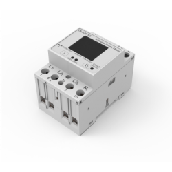
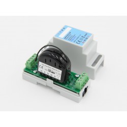
Shelly Qubino Wave Pro 1PM


Shelly Qubino Wave Pro 1PM
QPSW-0A1P16EU
Novo
Interruptor profissional de 1 canal Z-Wave inteligente para calha DIN com medição de potência, adequado para domótica e instalações com controlo remoto. Montagem em calha DIN no interior de uma caixa de disjuntores. Funções de segurança melhoradas.
Em estoque
- Retirar este produto da minha lista de favoritos.
- Adicionar este produto à minha lista de favoritos.
Características tecnicas
| Tecnologia | Z-Wave Serie 800 |
Informação alargada da Z-Wave (Inglês)
Nome: Wave Pro 1PM
Fabricante:Shelly Qubino
Identificador:QPSW-0A1P16EU
Número de Certificação Z-Wave :ZC14-24040420
Plataforma de Hardware :EFR32ZG23A
FLiRS:Não
Tipo de Role :Always On End Node
Descrição breve :Wave Pro 1PM is a DIN rail mountable smart switch with power measurement capabilities. It controls on/off function for one electrical device (with load up to 16 A), e.g., bulb, ceiling fan, IR heater, electrical locks, garage doors, irrigation system, etc. and it is compatible with push-buttons and switches (default).
Descrição :Wave Pro 1PM is a DIN rail mountable smart switch with power measurement capabilities. It controls on/off function for one electrical device (with load up to 16 A), e.g., bulb, ceiling fan, IR heater, electrical locks, garage doors, irrigation system, etc. and it is compatible with push-buttons and switches (default).
Grupo
Nodos máximos
Descrição
1
9
2
9
3
9
4
9
5
9
Número
Tamanho (Bytes)
Valor por defeito
Nome
Descrição
1
1
2
SW1 Switch type
0 push, 1 toggle state, 2 toggle change
120
4
0
Factory reset
Factory reset
17
1
0
Restore state of O1 after power failure
0 restore, 1 no restore
19
2
0
Turn O1 OFF Automatically with timer
1 - 32535, 0 disabled
2
1
2
SW2 Switch type
0 push, 1 toggle state, 2 toggle change
20
2
0
Turn O1 ON Automatically with timer
1 - 32535, 0 disabled
201
4
2147483647
Serial Number 1
Serial Number 1
202
4
2147483647
Serial Number 2
Serial Number 2
203
4
2147483647
Serial Number 3
Serial Number 3
23
1
0
O1 NO/NC
0 NO, 1 NC
25
1
0
Set timer units to Seconds or Milliseconds for O1
0 seconds, 1 milliseconds
36
1
50
O1 Power report on change - percentage
1-100 percentage, 0 disabled
39
1
30
O1 min reporting time
1-120 seconds, 0 disabled
91
4
0
Alarm conf. - Water
0 no action 1 open relay 2 close relay
92
4
0
Alarm conf. - Smoke
0 no action 1 open relay 2 close relay
93
4
0
Alarm conf. - CO
0 no action 1 open relay 2 close relay
94
4
0
Alarm conf. - Heat
0 no action 1 open relay 2 close relay
Association Group Information (AGI) V3
COMMAND_CLASS_ASSOCIATION_GRP_INFO_V3
Association V2
COMMAND_CLASS_ASSOCIATION_V2
Basic V2
COMMAND_CLASS_BASIC_V2
Binary Switch V2
COMMAND_CLASS_SWITCH_BINARY_V2
Configuration V4
COMMAND_CLASS_CONFIGURATION_V4
Device Reset Locally
COMMAND_CLASS_DEVICE_RESET_LOCALLY
Firmware Update Meta Data V5
COMMAND_CLASS_FIRMWARE_UPDATE_MD_V5
Indicator V3
COMMAND_CLASS_INDICATOR_V3
Manufacturer Specific V2
COMMAND_CLASS_MANUFACTURER_SPECIFIC_V2
Meter V6
COMMAND_CLASS_METER_V6
Multi Channel Association V3
COMMAND_CLASS_MULTI_CHANNEL_ASSOCIATION_V3
Notification V8
COMMAND_CLASS_NOTIFICATION_V8
Powerlevel
COMMAND_CLASS_POWERLEVEL
Security 0
COMMAND_CLASS_SECURITY
Security 2
COMMAND_CLASS_SECURITY_2
Supervision
COMMAND_CLASS_SUPERVISION
Transport Service V2
COMMAND_CLASS_TRANSPORT_SERVICE_V2
Version V3
COMMAND_CLASS_VERSION_V3
Z-Wave Plus Info V2
COMMAND_CLASS_ZWAVEPLUS_INFO_V2
Where to find S2 DSK on product
When adding the Device to a Z-Wave network with a gateway supporting Security 2 (S2), the PIN Code of the Z-Wave Device Specific Key (DSK) is required. You can find it on the label on the side of the Device and a copy is inserted in the packaging, which must not be lost. Do not remove the Z-Wave DSK label from the Device. As a backup measure, use the label in the packaging.
The first five digits of the key are highlighted or underlined to help the user identify the PIN Code part of the DSK text. The DSK is additionally represented with a QR Code as shown on the image.
The first five digits of the key are highlighted or underlined to help the user identify the PIN Code part of the DSK text. The DSK is additionally represented with a QR Code as shown on the image.
Classic Inclusion
6.1 Adding the Device to a Z-Wave® network (inclusion)
Note! All Device outputs (O, O1, O2, etc. - depending on the Device type) will turn the load 1s on/1s off /1s on/1s off if the Device is successfully added to/removed from a Z-Wave® network.
Note! In case of Security 2 (S2) adding (inclusion), a dialog will appear asking you to enter the corresponding PIN Code (5 underlined digits) that are written on the Z-Wave® DSK label on the side of the Device and on the Z-Wave® DSK label inserted in the packaging. IMPORTANT: The PIN Code must not be lost.
SmartStart adding (inclusion)
SmartStart enabled products can be added into a Z-Wave® network by scanning the Z-Wave® QR Code present on the Device with a gateway providing SmartStart inclusion. No further action is required, and the SmartStart device will be added automatically within 10 minutes of being switched on in the network vicinity.
1.With the gateway application scan the QR code on the Device label and add the Security 2 (S2) Device Specific Key (DSK) to the provisioning list in the gateway.
2.Connect the Device to a power supply.
3.Check if the blue LED is blinking in Mode 1. If so, the Device is not added to a Z-Wave® network.
4.Adding will be initiated automatically within a few seconds after connecting the Device to a power supply, and the Device will be added to a Z-Wave® network automatically.
5.The blue LED will be blinking in Mode 2 during the adding process.
6.The green LED will be blinking in Mode 1 if the Device is successfully added to a Z-Wave® network.
Adding (inclusion) with the S button
1.Connect the Device to a power supply.
2.Check if the blue LED is blinking in Mode 1. If so, the Device is not added to a Z-Wave® network.
3.Enable add/remove mode on the gateway.
4.To enter the Setting mode, quickly press and hold the S button on the Device until the LED turns solid blue.
5.Quickly release and then press and hold (> 2s) the S button on the Device until the blue LED starts blinking in Mode 3. Releasing the S button will start the Learn mode.
6.The blue LED will be blinking in Mode 2 during the adding process.
7.The green LED will be blinking in Mode 1 if the Device is successfully added to a Z-Wave® network.
Note! In Setting mode, the Device has a timeout of 10s before entering again into Normal mode.
Adding (inclusion) with a switch/push-button
1.Connect the Device to a power supply.
2.Check if the blue LED is blinking in Mode 1. If so, the Device is not added to a Z-Wave® network.
3.Enable add/remove mode on the gateway.
4.Toggle the switch/push-button connected to any of the SW terminals (SW, SW1, SW2, etc.) 3 times within 3 seconds (this procedure puts the Device in Learn mode*). The Device must receive on/off signal 3 times, which means pressing the momentary switch 3 times, or toggling the switch on and off 3 times.
5.The blue LED will be blinking in Mode 2 during the adding process.
6.The green LED will be blinking in Mode 1 if the Device is successfully added to a Z-Wave® network.
*Learn mode - a state that allows the Device to receive network information from the gateway.
Classic Exclusion
6.2 Removing the Device from a Z-Wave® network (exclusion)
Note! The Device will be removed from your Z-Wave® network, but any custom configuration parameters will not be erased.
Note! All Device outputs (O, O1, O2, etc. - depending on the Device type) will turn the load 1s on/1s off /1s on/1s off if the Device is successfully added to/removed from a Z-Wave® network.
Removing (exclusion) with the S button
1.Connect the Device to a power supply.
2.Check if the green LED is blinking in Mode 1. If so, the Device is added to a Z-Wave® network.
3.Enable add/remove mode on the gateway.
4.To enter the Setting mode, quickly press and hold the S button on the Device until the LED turns solid blue.
5.Quickly release and then press and hold (> 2s) the S button on the Device until the blue LED starts blinking in Mode 3. Releasing the S button will start the Learn mode.
6.The blue LED will be blinking in Mode 2 during the removing process.
7.The blue LED will be blinking in Mode 1 if the Device is successfully removed from a Z-Wave® network.
Note! In Setting mode, the Device has a timeout of 10s before entering again into Normal mode.
Removing (exclusion) with a switch/push-button
1.Connect the Device to a power supply.
2.Check if the green LED is blinking in Mode 1. If so, the Device is added to a Z-Wave® network.
3.Enable add/remove mode on the gateway.
4.Toggle the switch/push-button connected to any of the SW terminals (SW, SW1, SW2,…) 3 times within 3 seconds (this procedure puts the Device in Learn mode). The Device must receive on/off signal 3 times, which means pressing the momentary switch 3 times, or toggling the switch on and off 3 times.
5.The blue LED will be blinking in Mode 2 during the removing process.
6.The blue LED will be blinking in Mode 1 if the Device is successfully removed from a Z-Wave® network.
Factory Reset Procedure
6.3 Factory reset
Factory reset general
After Factory reset, all custom parameters and stored values (kWh, associations, routings, etc.) will return to their default state. HOME ID and NODE ID assigned to the Device will be deleted. Use this reset procedure only when the gateway is missing or otherwise inoperable.
Factory reset with the S button
Note! Factory reset with the S button is possible anytime.
1. To enter the Setting mode, quickly press and hold the S button on the Device until the LED turns solid blue.
2. Press the S button multiple times until the LED turns solid red.
3. Press and hold (> 2s) S button on the Device until the red LED starts blinking in Mode 3. Releasing the S button will start the factory reset.
4. During factory reset, the LED will turn solid green for about 1s, then the blue and red LED will start blinking in Mode 3 for approx. 2s.
5. The blue LED will be blinking in Mode 1 if the Factory reset is successful.
Factory reset with a switch/push-button
Note! Factory reset with a switch/push-button is only possible within the first minute after the Device is connected to a power supply.
1. Connect the Device to a power supply.
2. Toggle the switch/push-button connected to any of the SW terminals (SW, SW1, SW2,…) 5 times within 3 seconds. The Device must receive on/off signal 5 times, which means pressing the push-button 5 times, or toggling the switch on and off 5 times.
3. During factory reset, the LED will turn solid green for about 1s, then the blue and red LED will start blinking in Mode 3 for approx. 2s.
4. The blue LED will be blinking in Mode 1 if the Factory reset is successful.
Remote factory reset with parameter with a gateway
Factory reset can be done remotely with the settings in Parameter No. 120.
S2 Authenticated
S2_AUTHENTICATED
S2 Unauthenticated
S2_UNAUTHENTICATED
Color
If the product is only available in one color, pick the color from the list.
Electric Load Type
Select the electric load type(s) supported by the device.
Firmware Updatable
Indicates whether the firmware can be updated and whether it is done by the consumer or a technician.
Neutral Wire Required
For electric in-wall/wired switches, indicate whether a neutral wire is required for installation.
Switch Load Capacity Current
The amount of switch load energy the product is rated for in Amps
Switch Type
Describes the type of operator for a switch.