Sem produtos
Preços com IVA
Produto adicionado com sucesso ao seu carrinho de compras
Existem 0 produtos no seu carrinho de compras. Existe um produto no seu carrinho de compras.


 View larger

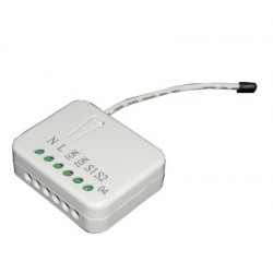
Fibaro Smart Module - micromódulo de relé simples sem potencial ON/OFF
FGS-214
Novo
O Módulo Inteligente Fibaro FGS-224 Z-Wave permitirá que você controle remotamente duas luzes, dispositivos ou contatos secos enquanto mantém seu switch existente.
Em estoque
- Retirar este produto da minha lista de favoritos.
- Adicionar este produto à minha lista de favoritos.

Características tecnicas
| Tecnologia | Z-Wave Plus |
Mais Informação
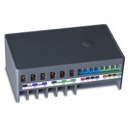
Relé duplo para ligar e desligar via rádio. Ele foi projetado para ser instalado em caixas de mecanismo padrão ao lado de um interruptor de parede, sendo compatível com o interruptor existente e sua estrutura.
Eles também podem ser montados em qualquer outro lugar necessário para operar dois dispositivos independentes de energia combinada de 1,5 kW. O Fibaro Dual On/Off Relay pode ligar ou desligar dispositivos conectados por meio de ondas de rádio ou interruptores de parede conectados diretamente.
Micromódulo de comutação Z-Wave+ Módulo Inteligente FIBARO
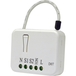
O micromódulo Smart FIBARO foi projetado para ativar e desativar dispositivos elétricos. Graças ao seu pequeno tamanho, pode ser instalado em caixas de junção ou caixas de embutir. O módulo é controlado pela rede Wave Z ou por um simples switch. Conecte seu FIBARO Smart Module ao seu sistema Z-Wave e outros dispositivos para desfrutar de possibilidades quase infinitas!
Este módulo possui dois relés livres de potencial (contato seco) com função de temporizador (para criar um impulso), de modo que pode ser usado tanto para comutar uma tensão convencional de 230V quanto qualquer tipo de fonte de alimentação CC (5V, 12V ... 24 Vcc). Portanto, pode ser usado para controlar qualquer tipo de carga, como uma caldeira (ligando o contato seco em vez de um termostato) ou um operador de porta de garagem...
Além disso, possui uma função para evitar a ativação simultânea dos 2 relés, essencial em determinadas aplicações para evitar curtos-circuitos.
Blocos de terminais práticos - Instalação fácil
O FIBARO Smart Module está equipado com plugues de seção transversal aumentada que permitem conectá-lo a cabos de maior diâmetro e simplificar o processo de instalação.
Menu de configuração amigável
O diodo RGB integrado é uma ajuda valiosa durante o processo de instalação. A luz mostrará se o FIBARO Smart Module foi adicionado ou removido da rede. Você também pode ver se uma calibração ou atualização foi bem-sucedida.
Testador de cobertura de rede de onda Z
Use o FIBARO Smart Module para verificar a qualidade do sinal na rede Waves Z. O LED RGB integrado o ajudará a verificar se o local selecionado para instalação está dentro do seu alcance.
Atualizações de software
Você pode atualizar seu software FIBARO Smart Module para a versão mais recente assim que estiver disponível. Dessa forma, você tem acesso aos recursos mais recentes sem precisar comprar a versão mais recente do dispositivo.
fácil de instalar
Basta colocar o módulo na caixa traseira e conectá-lo a uma instalação existente. O tamanho em miniatura do módulo permite que ele seja colocado em muitos lugares convenientes.
gerenciamento de cena
Mesmo as ações mais complexas podem ser ativadas por um interruptor de parede conectado a um módulo. Com um simples toque no botão ao entrar em uma sala, é tão natural quanto acender as luzes. 1 a 3 toques e um toque longo podem ser atribuídos a quatro ações diferentes
Seu dispositivo móvel é seu controle remoto
Você pode controlar os módulos e receber informações através de seus computadores pessoais e dispositivos móveis. O FIBARO Single Switch 2 não requer painéis de controle caros para operar.
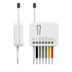
Cuidado, este módulo requer neutralidade para funcionar.
FUNÇÕES:
Controle duas luzes/dispositivos remotamente
Pode ser instalado atrás de um switch existente (bi-estável ou monoestável)
Função LIGAR/DESLIGAR
Dois relés sem potencial (controle de porta, caldeira, porta de garagem, etc.)
Integra o chip da série Z-Wave 500
Comunicação 250% mais rápida em comparação com os dispositivos Onda Z padrão.
Mecanismo de ativação de cena integrado (via S2)
Classes de comunicação e notificação de segurança
Menu de configuração com um diodo
Suporta modo seguro (Z-Wave Network Security) criptografado com codificação AES-128
Testador de cobertura de rede Wave Z integrado
Atualização de software OTA (dependente do driver)
Blocos de terminais maiores para fácil fiação
Forma arredondada para atender aos mais altos padrões
Pequeno, discreto e estético
Facilidade de uso e instalação
DADOS TÉCNICOS :
Tipo de Módulo: Receptor de Onda Z
Fonte de alimentação: 100 - 240V~, 50/60Hz ou 24 - 30Vdc
Fiação: 3 fios, é necessário um neutro (em 230V)
Força maxima:
Corrente máxima por saída: 6A / 110 - 240V~, 50/60Hz (difere de acordo com o tipo de carga)
Corrente total máxima: 9,5A / 110 - 240V~, 50/60Hz (difere de acordo com o tipo de carga)
Frequência: 868,42Mhz
Distância de transmissão: 50m de campo livre, 40m dentro de casa (depende da estrutura do edifício)
Potência do sinal: 1mW
Dimensões: 42,5 mm x 38,25 mm x 20,3 mm (C x L x A)
Temperatura de operação: 0-35°C
Normas: CE, ROHS, 2011/65/UE, 2014/53/UE, 2015/863, ZWAVE PLUS
Toda a documentação e manuais do produto Fibaro estão disponíveis em manuals.fibaro.com.
Informação alargada da Z-Wave (Inglês)
Descarregue o manual a partir de aqui.
part of the DSK (label on the bottom of the box).
1. Power the device.
2. Set the main controller in (Security/non-Security Mode) add mode
(see the controller’s manual).
3. Quickly, three times click button connected to S1/S2 or the
maintenance button.
4. LED will start blinking yellow, wait for the adding process to end.
5. If you are adding in Security S2 Authenticated, input the underlined
part of the DSK (label on the bottom of the box).
6. Adding result will be confirmed by the Z-Wave controller’s message
and the LED:
• Green – successful (non-secure, S0, S2 non-authenticated),
• Magenta – successful (Security S2 Authenticated),
• Red – not successful.
1. Power the device.
2. Set the main controller into remove mode (see the controller’s
manual).
3. Quickly, three times click the maintenance button.
4. LED will start blinking yellow, wait for the removing process to
end.
5. Successful removing will be confirmed by the Z-Wave controller’s
message and red LED colour.
2. Release button when the device glows yellow.
3. Quickly click the button to confirm.
4. After few seconds the device will be restarted, which is signalled
with red LED colour.
Avaliações
Buen rele
Es bueno. Gracias
Rele contacto seco
Es la version de contacto seco del rele z-wave de Fibaro. Hay que cambiar paramentros segun el uso. Ojo.
30 outros produtos na mesma categoria:
-
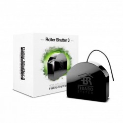
Bypass para...
-
Qubino...
-
Qubino...
-
Philio...
-
AEOTEC -...
-
AEOTEC -...
-
AEOTEC -...
-
Aeotec Nano...
-
Aeotec Nano...
-
Qubino Mini...
-
Dimmer...
-
Chave de...
-
WiDom Smart...
-
Qubino...
-
Micromódulo...
-
Controlador...
-
FIBARO...
-
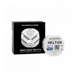
HELTUN -...
-
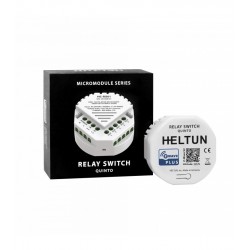
HELTUN -...
-
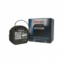
Heatit ZM...
-
Philio...
-
ZOOZ...
-
Philio...
-
Philio...
-
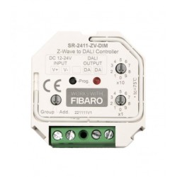
Controlador...
-
Heatit ZM...
-
Termostato...
-
Shelly...
-
Shelly...
-
Shelly...