Sem produtos
Preços com IVA
Produto adicionado com sucesso ao seu carrinho de compras
Existem 0 produtos no seu carrinho de compras. Existe um produto no seu carrinho de compras.


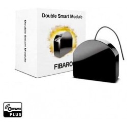
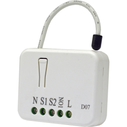
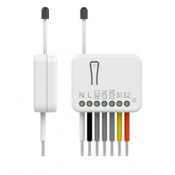
Fibaro - Chave Dupla 2 - Micromódulo Relé Duplo Ligado / Desligado Z-Wave + com Medição de Consumo
FGS-223
Novo
O relé / chave do micromódulo Fibaro FGS-223 "Double Switch 2" permitirá que você controle duas luzes ou dois dispositivos remotos enquanto mantém a chave convencional existente.
Em estoque
- Retirar este produto da minha lista de favoritos.
- Adicionar este produto à minha lista de favoritos.

Características tecnicas
| Tecnologia | Z-Wave Plus |
| Recurso | Medição de Consumo |
Mais Informação
O novo micro-módulo de interruptor / relé duplo da Fibaro, Fibaro FGS-223 "Chave dupla 2" disponível como uma chave Z-Wave dupla, foi projetado para ativar e desativar dispositivos elétricos ou cargas. Graças ao seu pequeno tamanho, ele pode ser montado em caixas de conexão ou caixas de dispositivos em ambientes internos. O módulo é controlado pela rede Z-Wave ou por um simples switch. Tem a função de medir a potência e o consumo de energia de uso que permite controlar e reduzir a sua fatura de luz. Conecte seu Fibaro FGS-223 "Double Switch 2" no sistema junto com outros dispositivos para desfrutar das possibilidades quase infinitas!
Por se tratar de 1 relé duplo, possui 2 saídas:
- 6,5 A (1.560 W a 240 V) máx. por saída com carga resistiva.
- 10A (2.400 W a 240 V) máx. por TOTAL de saída com carga resistiva.
Possui um mecanismo de gatilho de cena embutido
aulas de comunicação e notificação de segurança
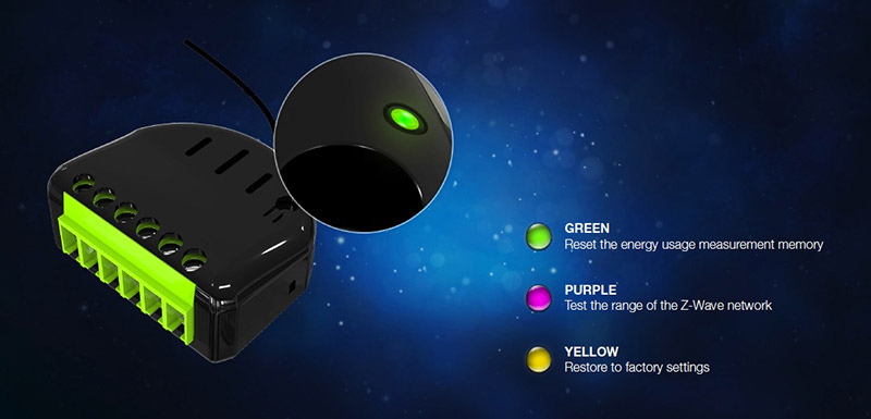
menu de configuração com um diodo
Z-Wave de última geração com chip da série 500
Compatível com Z-Wave Plus
Executa funções de repetidor Z-Wave
Mede a energia e potência dos dispositivos conectados
Suporta modo de segurança (Z-Wave Security Network) com criptografia AES-128
Um sistema de controle complexo para cada canal
Um sistema de ativação de cena complexo para cada canal (gerenciamento de cena)
1 a 3 pressões e mantendo a tecla pressionada podem ser atribuídos a quatro ações diferentes
medição de potência muito precisa +/- 1% de potência acima de 5W
Notificações inteligentes
Conexões aprimoradas
menu de configuração simples
Tem uma testemunha de teste de cobertura da rede Z-Wave
Atualizações de software*
compatibilidade com certificação confirmada por FCC, DEKRA, Z-Wave
Atenção:
Observe que este módulo requer NEUTRO para operar. A saída não é livre de potencial, o que torna impossível controlar um contato seco ou carregar outra tensão de alimentação de entrada.
REPETIMOS: ele não pode ser usado em um esquema de conexão do tipo "contato seco", como seu predecessor, o Fibaro FGS-222, poderia.
Diagrama de fiação do relé Fibaro FGS-223
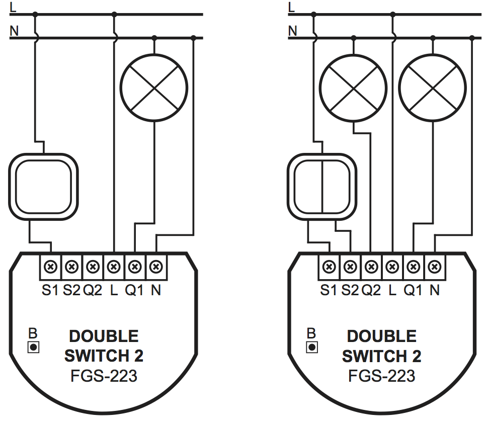
Imagem de fiação com 1 e 2 circuitos
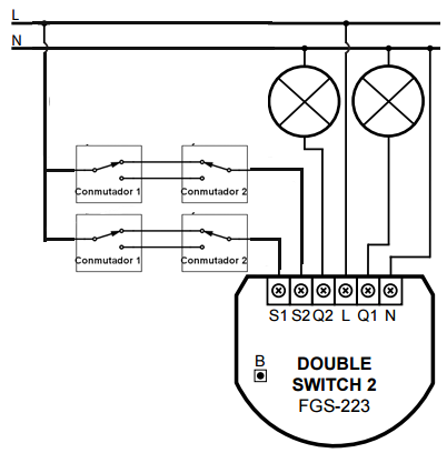
Diagrama de conexão para controlar 1 zona de iluminação com "chaves comutadas":
Resumo:
2 saídas:
- 6,5 A (1560 W a 240 V) máx. por saída com carga resistiva.
- 10 A (2400 W a 240 V) máx. por TOTAL de saída com carga resistiva.
medição precisa do consumo (+/- 1% de 5W).
Série Z-Wave + 500 (melhor comunicação remota).
comunicações seguras com criptografia AES-128.
Capacidade de acionar cenas de automação residencial * através das entradas S1 e S2 (4 cenas possíveis por botão).
Função de repetidor para estender a rede Z-Wave.
Configuração com função de menu interativo e testador de rede Z-Wave com LED
 |
Informação alargada da Z-Wave (Inglês)
Descarregue o manual a partir de aqui.
Active power and energy metering functionality
Z-Wave range tester
LED diode
2) Make sure the Switch 2 is within the direct range of your Z-Wave controller.
3) Connect the device in accordance with one of the diagrams included in the manual.
4) After verifying correctness of the connection switch on the mains voltage.
5) Identify the S1 switch or the B-button (located on the device’s housing).
6) Set the main controller in (security/non-security) add mode (see the controller’s manual).
7) Quickly, three times press the S1 switch or the B-button.
8) Wait for the adding process to end.
9) Successful adding will be confirmed by the Z-Wave controller’s message.
2) Identify the S1 switch or the B-button (located on the device’s housing).
3) Set the main controller in remove mode (see the controller’s manual).
4) Quickly, three times press the S1 switch or the B-button.
5) Wait for the removing process to end.
6) Successful removing will be confirmed by the Z-Wave controller’s message.
1) Switch off the mains voltage (disable the fuse).
2) Remove the Switch 2 from the wall switch box.
3) Switch on the mains voltage.
4) Press and hold the B-button to enter the menu.
5) Wait for the visual LED indicator to glow yellow.
6) Quickly release and click the B-button again.
7) After few seconds the device will be restarted, which is signalled with the red LED indicator colour.
Use reset procedure only if the primary controller is missing or inoperable.
Avaliações
Domtizar luces
Buen rele para domotizar luces encendido/apagado. Facil de parametrizar para pulsador con los parametros Z-Wave
Envio rapido
Asesoramiento correcto. Envio rapido y bien.
30 outros produtos na mesma categoria:
-
Qubino...
-
Qubino...
-
Philio...
-
AEOTEC -...
-
AEOTEC -...
-
AEOTEC -...
-
Aeotec Nano...
-
Aeotec Nano...
-
Qubino Mini...
-
Dimmer...
-
Chave de...
-
WiDom Smart...
-

Qubino...
-
Fibaro...
-
Micromódulo...
-
Controlador...
-
FIBARO...
-
HELTUN -...
-
HELTUN -...
-
Heatit ZM...
-
Philio...
-
ZOOZ...
-
Philio...
-
Philio...
-
Controlador...
-
Heatit ZM...
-
Termostato...
-
Shelly...
-
Shelly...
-
Shelly...