No products
Prices are tax included
Product successfully added to your shopping cart
There are 0 items in your cart. There is 1 item in your cart.


 View larger

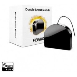
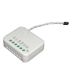
Fibaro Smart Module - ON/OFF simple potential-free relay micromodule
FGS-214
New
The Fibaro FGS-224 Z-Wave Smart Module will allow you to control two lights, devices or dry contacts remotely while maintaining your existing switch.
In Stock
- Remove this product from my favorite's list.
- Add this product to my list of favorites.

Technical characteristics
| Technology | Z-Wave Plus |
More info
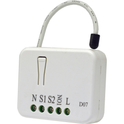
Double relay for on and off via radio. It is designed to be installed in standard mechanism boxes next to a wall switch, being compatible with the existing switch and its frame.
They can also be mounted anywhere else needed to operate two independent 1.5kW combined power devices. The Fibaro Dual On/Off Relay can turn connected devices on or off either via radio waves or directly connected wall switches.
FIBARO Smart Module Z-Wave+ Switching Micromodule
The Smart FIBARO micromodule has been designed to activate and deactivate electrical devices. Thanks to its small size, it can be installed in junction boxes or flush-mounted boxes. The module is controlled by the Wave Z network or by a simple switch. Connect your FIBARO Smart Module to your Z-Wave system and other devices to enjoy almost endless possibilities!
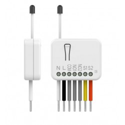
This module has two potential-free relays (dry contact) with a timer function (to create an impulse), so it can be used both to switch a conventional voltage of 230V and any type of DC power supply (5V, 12V ... 24V DC). Therefore, it can be used to control any type of load such as a boiler (by connecting the dry contact instead of a thermostat) or a garage door operator...
In addition, it has a function to prevent the simultaneous activation of the 2 relays, essential in certain applications to avoid short circuits.
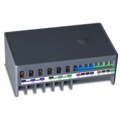
Practical Terminal Blocks - Easy Installation
The FIBARO Smart Module is equipped with plugs of increased cross section that allow you to connect it to larger diameter cables and simplify the installation process.
User-friendly setup menu
The integrated RGB diode is a valuable aid during the installation process. The light will show if the FIBARO Smart Module has been added or removed from the network. You can also see if a calibration or update has been successful.
Z wave network coverage tester
Use the FIBARO Smart Module to check the signal quality on the Waves Z network. The built-in RGB LED will help you check if the location you have selected for installation is within your range.
Software updates
You can update your FIBARO Smart Module software to the latest version once it is available. This way you have access to the latest features without having to buy the latest version of the device.
easy to install
Simply place the module in the back box and connect it to an existing installation. The miniature size of the module allows it to be placed in many convenient places.
scene management
Even the most complex actions can be activated by a wall switch connected to a module. With a simple push of the button when entering a room, it's as natural as turning on the lights. 1 to 3 presses and a long press can be assigned to four different actions
Your mobile device is your remote
You can control the modules and receive information through your personal computers and mobile devices. FIBARO Single Switch 2 does not require expensive control panels to operate.
Caution, this module requires neutrality to work.
FUNCTIONS:
Control two lights/devices remotely
Can be installed behind an existing switch (bi-stable or monostable)
ON/OFF function
Two potential-free relays (door control, boiler, garage door, etc.)
Integrates the Z-Wave 500 series chip
250% faster communication compared to standard Onda Z devices.
Built-in scene activation mechanism (via S2)
Classes of communication and security notification
Configuration menu with a diode
Supports secure mode (Z-Wave Network Security) encrypted with AES-128 coding
Integrated Wave Z network coverage tester
Software update OTA (driver dependent)
Larger terminal blocks for easy wiring
Rounded shape to meet the highest standards
Small, discreet and aesthetic
Ease of use and installation
TECHNICAL DATA :
Module Type: Z Wave Receiver
Power supply: 100 - 240V~, 50/60Hz or 24 - 30 Vdc
Wiring: 3 wires, a neutral is required (at 230V)
Maximum power:
Maximum current per output: 6A / 110 - 240V~, 50/60Hz (differs depending on the type of load)
Maximum total current: 9.5A / 110 - 240V~, 50/60Hz (differs depending on the type of load)
Frequency: 868.42Mhz
Transmission distance: 50m free field, 40m indoors (depends on the building structure)
Signal power: 1mW
Dimensions: 42.5mm x 38.25mm x 20.3mm (L x W x H)
Operating temperature: 0-35°C
Standards: EC, ROHS, 2011/65/EU, 2014/53/EU, 2015/863, ZWAVE PLUS
All documentation and manuals for the Fibaro product are available at manuals.fibaro.com.
Extended Z-Wave info
Manual download HERE.
part of the DSK (label on the bottom of the box).
1. Power the device.
2. Set the main controller in (Security/non-Security Mode) add mode
(see the controller’s manual).
3. Quickly, three times click button connected to S1/S2 or the
maintenance button.
4. LED will start blinking yellow, wait for the adding process to end.
5. If you are adding in Security S2 Authenticated, input the underlined
part of the DSK (label on the bottom of the box).
6. Adding result will be confirmed by the Z-Wave controller’s message
and the LED:
• Green – successful (non-secure, S0, S2 non-authenticated),
• Magenta – successful (Security S2 Authenticated),
• Red – not successful.
1. Power the device.
2. Set the main controller into remove mode (see the controller’s
manual).
3. Quickly, three times click the maintenance button.
4. LED will start blinking yellow, wait for the removing process to
end.
5. Successful removing will be confirmed by the Z-Wave controller’s
message and red LED colour.
2. Release button when the device glows yellow.
3. Quickly click the button to confirm.
4. After few seconds the device will be restarted, which is signalled
with red LED colour.
Reviews
Buen rele
Es bueno. Gracias
Rele contacto seco
Es la version de contacto seco del rele z-wave de Fibaro. Hay que cambiar paramentros segun el uso. Ojo.
30 other products in the same category:
-
Bypass for...
-
Qubino...
-
Qubino...
-
Philio...
-
AEOTEC -...
-
AEOTEC -...
-
Aeotec...
-
Aeotec Nano...
-
Aeotec Nano...
-
Qubino Mini...
-
WiDom Smart...
-
WiDom Smart...
-
WiDom Smart...
-
Qubino...
-
Micromodule...
-
FIBARO RGBW...
-
FIBARO...
-
HELTUN -...
-
HELTUN -...
-
Heatit ZM...
-
Philio...
-
ZOOZ...
-
Philio...
-
Philio...
-
Z-Wave to...
-
Heatit ZM...
-
Heatit ZM...
-
Shelly...
-
Shelly...
-
Shelly...